
Disassembling and assembling device for heavy wheel

A wheel and heavy-duty technology, which is applied in the field of heavy-duty wheel disassembly and assembly devices, can solve the problems of high labor intensity in disassembly and assembly of wheels, difficulty in moving and centering, and poor stress conditions, so as to facilitate vehicle-mounted and field use, improve stress conditions, The effect of high centering rate

Inactive Publication Date: 2010-11-24
WUHAN UNIV OF SCI & TECH
View PDF5 Cites 3 Cited by
  • Summary
  • Abstract
  • Description
  • Claims
  • Application Information

AI Technical Summary

Problems solved by technology

When installing the tire, the repairman manually lifts the wheel for installation, therefore, the disassembly and assembly of the wheel is labor-intensive and inefficient
[0003] At present, most of the replacement tools used for dismounting wheels are fork-type wheel removal tools. The wheels are supported by the fork, and the lifting and lowering of the fork can only realize the lifting of the wheel during installation and disassembly, that is, the movement in the vertical direction. in the middle, but it is difficult to move in the horizontal direction
In addition, because the suspension fork of this type of wheel removal tool is a cantilever structure, its stress conditions are poor, its structure rigidity is low, and it is heavy. or field replacement

Method used


Image

  • Disassembling and assembling device for heavy wheel
  • Disassembling and assembling device for heavy wheel
  • Disassembling and assembling device for heavy wheel

Examples


Embodiment 1

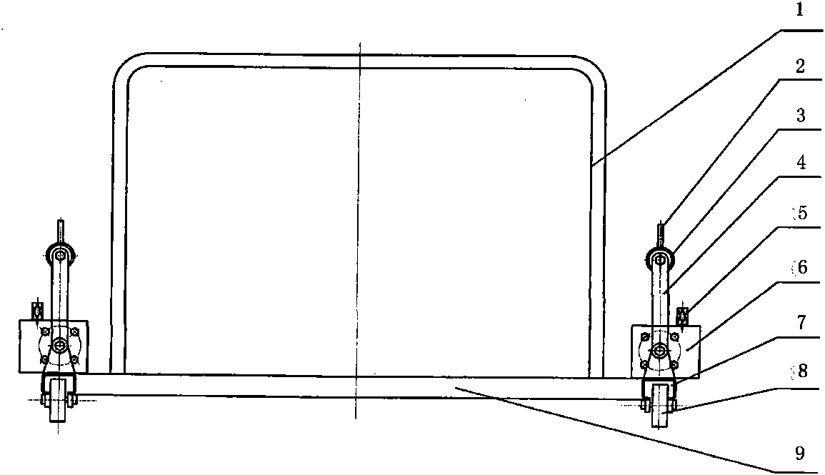
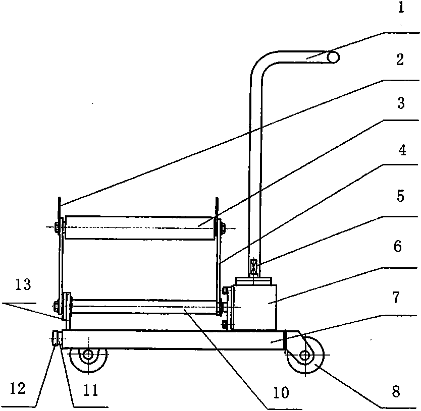
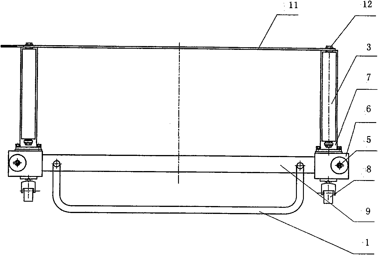
[0015] A heavy-duty wheel dismounting device: such as figure 1 and image 3 As shown, two side supports 7 are symmetrically fixed on the two ends of the crossbeam 9, and the two side supports 7 are respectively perpendicular to the crossbeam 9 on the horizontal plane to form a "U" shaped frame, and the crossbeam 9 is equipped with handrails 1, two Rollers 8 are respectively housed below the two ends of the side support 7 . For convenience of description, it is assumed that the open end of the "U" shape frame is the front end, and the end where the armrest 1 is housed is the rear end. The two speed reducers 6 are mounted on one end (rear end) of the two side brackets 7 respectively, and the other end (front end) of the two side brackets 7 are respectively provided with a short pin shaft 12, and the additional pull rod 11 is movably stuck on the On the two short pin shafts 12.

[0016] Such as figure 2 As shown, the two swing link shafts 10 are respectively installed above ...

Embodiment 2

[0019] A heavy-duty wheel dismounting device: the input end 5 of the reducer 6 is driven by a motor. All the other are with embodiment 1.

[0020] The U"-shaped frame of this specific embodiment is a simply-supported structure supported by rollers 8, which greatly improves the stress conditions, easily realizes miniaturization and light weight, and is convenient for vehicle and field use, especially for the side bracket 7 to fork into the lower part of the tire; The two rotating rollers 3 can realize the rotation of the wheel around the central axis of the tire when the tire is installed, and then realize the centering of the rim screw hole; the handrail installed on the U" frame can conveniently make the device move forward and backward; the set Additional tie rod 11 can increase the rigidity of U-shaped frame horizontal plane.

[0021] The swing angle of the swing link 4 is controlled by the reducer 6 to drive the swing link shaft 10, which can realize the left and right or...


PUM


Abstract

The invention relates to a disassembling and assembling device for a heavy wheel. The technical scheme is that: two side brackets [7] are symmetrically fixed on the two ends of a beam [9] to form a U-shaped frame; rollers [8] are arranged below the two ends of the two side brackets [7] respectively; two speed reducers [6] are arranged at one end of each of the two side brackets [7] respectively; an additional pull rod [11] is movably clamped on a short pin shaft [12]; the beam [9] is provided with a handrail [1]; two oscillating bar shafts [10] are arranged in parallel above the two side brackets [7] respectively; one end of each oscillating bar shaft [10] is connected with the output end of the corresponding speed reducer [6], and the other end of the oscillating bar shaft [10] is arranged in a corresponding bearing seat [13] respectively; and the upper ends of oscillating bars [4] fixedly arranged at the two ends of each oscillating bar shaft [10] are provided with rotary rollers [3] respectively. The device has the characteristics of high centering rate, convenient disassembly and assembly, high stability, safety, reliability and contribution to vehicle mounting and field use.

Description

technical field [0001] The invention belongs to the technical field of wheel dismounting devices. Specifically relates to a heavy-duty wheel dismounting device. Background technique [0002] The wheels of heavy-duty vehicles and large-scale construction machinery have large volume and weight, and the wheels wear quickly. In order to ensure the normal use of the tires, the wheels need to be replaced regularly, and the wheels must be replaced after the tires are damaged. When the wheel is disassembled, after the fixing bolts are loosened, the wheel is manually taken off by the repairman. When the tire is installed, the wheel is manually lifted by the repairman for installation. Therefore, the disassembly and assembly of the wheel is labor-intensive and inefficient. [0003] At present, most of the replacement tools used for dismounting wheels are fork-type wheel removal tools. The wheels are supported by the fork, and the lifting and lowering of the fork can only realize the...

Claims


Application Information

Patent Timeline
Patent Type & Authority Applications(China)
IPC IPC(8): B60B29/00
Inventor 张洪汛吴小珍勾频高俊
Owner WUHAN UNIV OF SCI & TECH
Learn More