Production line diverging conveying framework and traverse conveyer belt platform thereof

A diversion conveying and conveyor belt technology, applied in the direction of conveyor objects, transportation and packaging, furnaces, etc., can solve the problems of production line output speed dragging, output reduction, slow transmission speed, etc., and achieve faster production line diversion efficiency , The effect of increasing output

Active Publication Date: 2010-11-24
TCL CHINA STAR OPTOELECTRONICS TECH CO LTD
View PDF7 Cites 24 Cited by
  • Summary
  • Abstract
  • Description
  • Claims
  • Application Information

AI Technical Summary

Problems solved by technology

[0004] However, this architecture has the problem of slow transfer speed
Because the traversing conveyor belt platform 93 can only accept one product 81 from the front delivery end 90 at a time, the next product 82 must wait for the previous product 81 to be delivered before flowing into the traversing conveyor belt platform 92, so , the output speed of the entire production line is bound to be dragged down, resulting in a reduction in output

Method used


Image

  • Production line diverging conveying framework and traverse conveyer belt platform thereof
  • Production line diverging conveying framework and traverse conveyer belt platform thereof
  • Production line diverging conveying framework and traverse conveyer belt platform thereof

Examples


Embodiment Construction

[0026] In order to make the above-mentioned purposes, features and advantages of the present invention more obvious and understandable, the preferred embodiments of the present invention will be specifically cited below, together with the accompanying drawings, for a detailed description as follows:

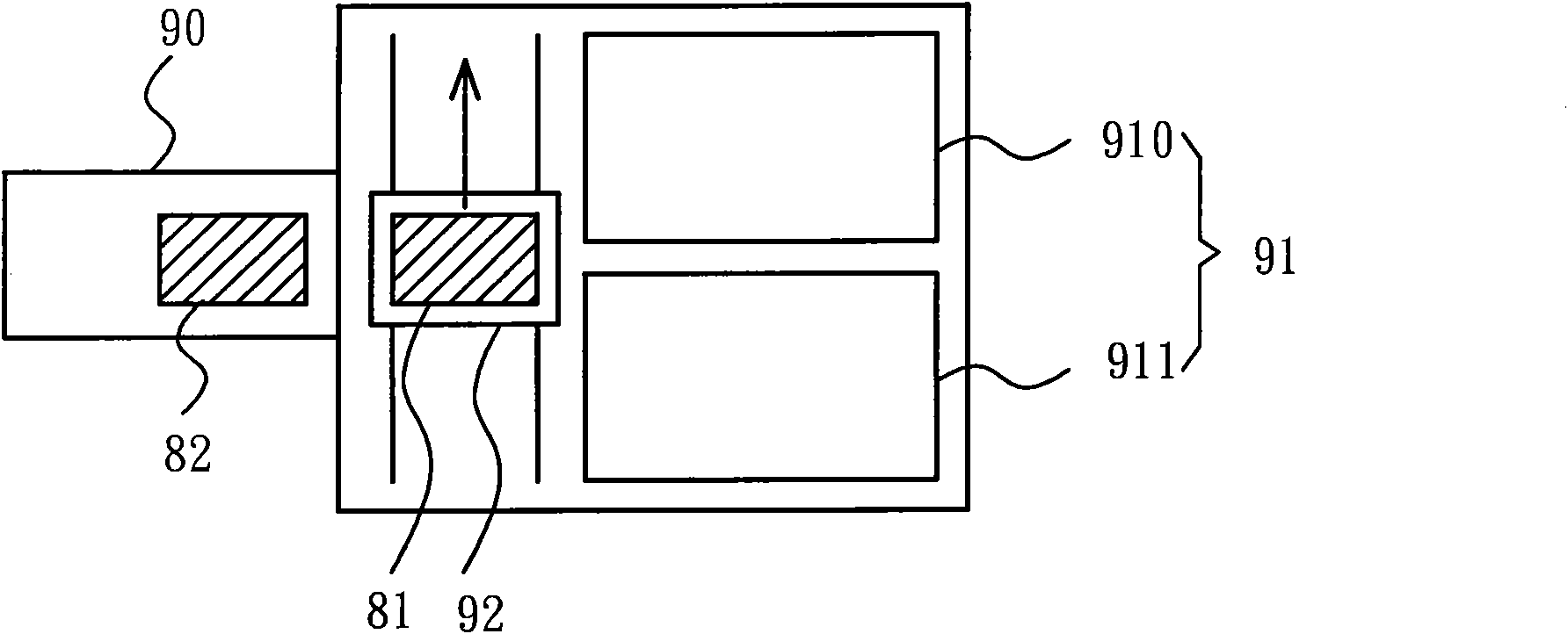
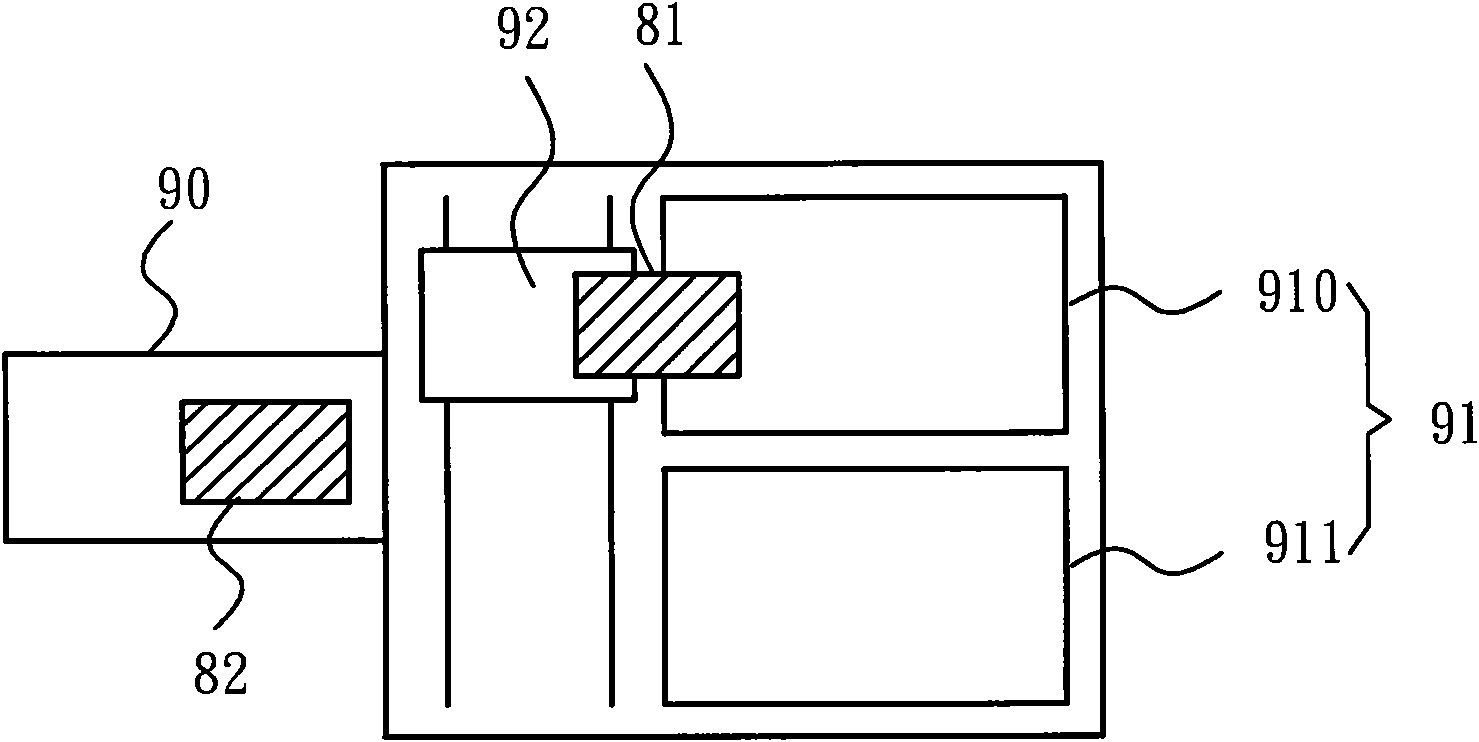
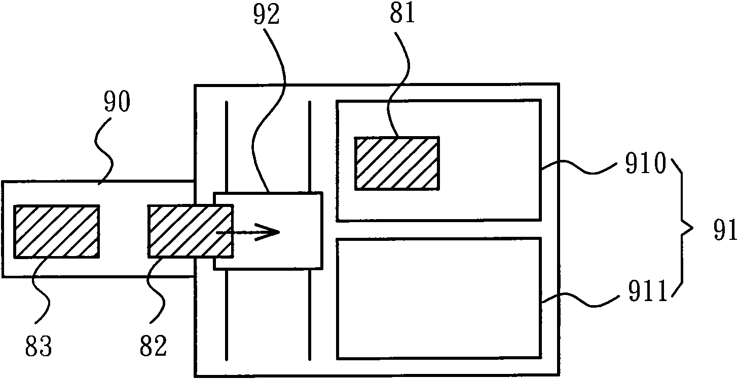
[0027] Please refer to Figures 3A to 3C As shown, it discloses a schematic diagram of the diversion operation of the production line diversion conveying structure of the preferred embodiment of the present invention. The production line diversion conveying structure mainly includes a front conveying end 10, a first rear conveying end 20, and a second rear conveying end 21 and a traversing conveyor belt platform 30. The present invention will use a preferred embodiment to describe the above-mentioned components in detail below.

[0028] Please refer to Figures 3A to 3C As shown, the front conveying end 10 of the preferred embodiment of the present invention is the output end o...


PUM


Abstract

The invention discloses a production line diverging conveying framework and a traverse conveyer belt platform thereof. The production line diverging conveying framework is composed of a front conveying end, two back conveying ends and a traverse conveyer belt platform, wherein the traverse conveyer belt platform is arranged between the front conveying end and the back conveying ends, and consists of two sets of paralleled transport mechanisms which respectively correspond to the back conveying ends. When the traverse conveyer belt platform moves to and fro, and the two sets of transport mechanisms can carry products from the front conveying end in sequence, and then transport the products to the corresponding back conveying ends in sequence. Because the two sets of transport mechanisms can be used in the same traverse conveyer belt platform and respectively transport and receive products in each to-and-fro movement, the production line diverging efficiency can be effectively increased.

Description

【Technical field】 [0001] The present invention relates to a production line diversion conveying structure and its traversing conveyor belt platform, in particular to a production line diversion conveying structure and its traversing conveyor belt platform which can effectively increase the production line diversion efficiency. 【Background technique】 [0002] Nowadays, in order to expand the production line capacity of finished or semi-finished products of flat-panel displays, the technology industry has developed a production line diversion structure from single conveyor belt (conveyer) to double conveyor belt. Please refer to Figure 1A to Figure 1D As shown, it is a schematic diagram of the diversion action of the aforementioned existing production line diversion structure, which includes a front conveying end 90, two rear conveying ends 91, and a traverse conveyor belt platform 92. The front conveying end 90 is loaded with several Conveyed products 81-83, such as liquid cr...

Claims


Application Information

Patent Timeline
Patent Type & Authority Applications(China)
IPC IPC(8): B65G47/68B65G49/06
CPCB65G49/064B65G47/642
Inventor 贺成明潘昶宏
Owner TCL CHINA STAR OPTOELECTRONICS TECH CO LTD
Why Eureka
Try Eureka