
Water diversion channel device for coal mine and using method thereof

A water diversion tank and coal mine technology, applied in safety devices, drainage, mining equipment, etc., can solve problems such as complex structure, inconvenient operation, waste of water sources, etc., and achieve the effects of low operation error rate, high diversion efficiency, and convenient operation

Pending Publication Date: 2021-07-23
BEIJING TIANDI HUATAI MINING MANAGEMENT CO LTD +1
View PDF0 Cites 0 Cited by
  • Summary
  • Abstract
  • Description
  • Claims
  • Application Information

AI Technical Summary

Problems solved by technology

In the prior art, the water diversion tank device is poorly sealed, and when diverting water, it is easy to mix clean water and sewage, resulting in waste of water; or the operation is inconvenient and the stability is not good, which makes the water diversion tank device inconvenient to use; or the structure is too Complicated and cost-effective

Method used


Image

  • Water diversion channel device for coal mine and using method thereof
  • Water diversion channel device for coal mine and using method thereof
  • Water diversion channel device for coal mine and using method thereof

Examples


Embodiment 1

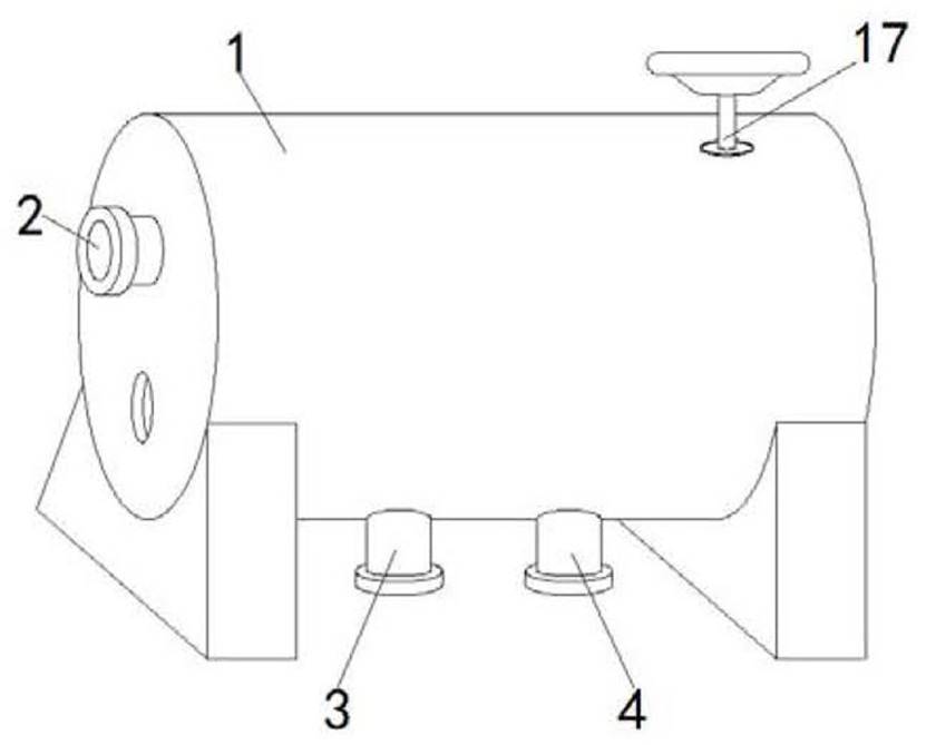
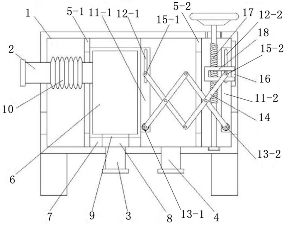
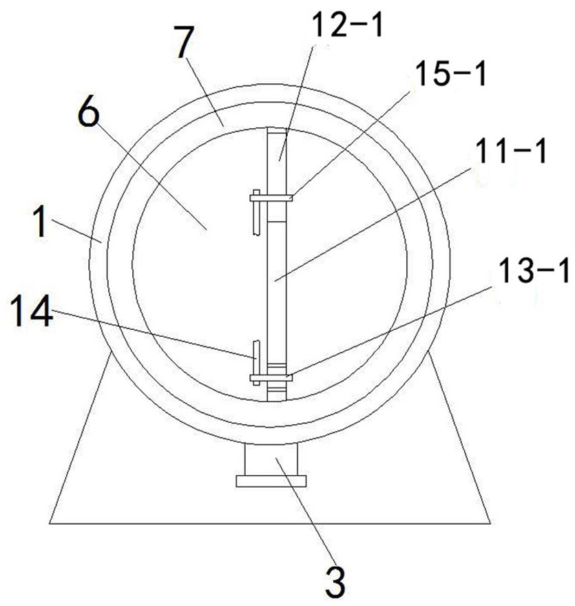
[0026] like Figure 1~3 A water diversion tank device for coal mine is shown, which includes a casing 1, the front end of the casing 1 is connected with a liquid inlet pipe 2, the bottom of the casing 1 is fixed with a support, and the front and rear sides of the casing 1 are provided with air holes. The first water outlet pipe 3 and the second water outlet pipe 4 are connected to the front and back of the lower part of the housing 1 in sequence, and a first stop ring 5-1 and a second The limit ring 5-2, the position of the first water outlet pipe 3 and the second water outlet pipe 4 are between the two limit rings, a movable water tank 6 is arranged between the two limit rings, and the lower cover of the water tank 6 There is a sealing block 7 attached to the lower wall of the housing 1, the inner wall of the housing 1 is a smooth wall (to facilitate the movement of the box and the bonding of the sealing block), the middle part of the sealing block 7 is provided with a throug...

Embodiment 2

[0037] Present embodiment is the method for adopting the device in embodiment 1 to divert clear water and sewage, and concrete operation is as follows:

[0038] 1) When the liquid to be transported is clean water, the liquid enters the inside of the water tank 6 through the liquid inlet pipe 2 and the telescopic pipe 10, and then the liquid passes through the perforation 9 and the through hole 8 in sequence and is exported from the first outlet pipe 3;

[0039] 2) When the liquid to be transported is sewage, turn the handwheel on the screw 17 to make the U-shaped piece 18 slide up along the chute 16, and the U-shaped piece 18 drives the second round rod 15-2 along the second sliding hole 12-2 Slide up so that the scissors frame 14 drives the first rotating shaft 13-1 close to the second rotating shaft 13-2, the first rotating shaft 13-1 drives the first vertical block 11-1 to move backward, and the first vertical block 11-1 drives the water tank 6 behind The water tank 6 drive...


PUM


Abstract

The invention discloses a water diversion channel device for a coal mine and a using method thereof. The water diversion channel device comprises a shell; the front end of the shell is connected with a liquid inlet pipe, and the lower portion of the shell is connected with two water outlet pipes; and limiting rings, a movable water tank, a sealing block with a through hole, a shear shank and a series of assemblies driving the shear shank to stretch out and draw back are arranged in an inner cavity of the shell. A screw rotates to drive the series of assemblies, so that the shear shank stretches out and draws back, and then the water tank is driven to move front and back to be communicated with the two water outlet pipes, so that different liquids are shunted. The device is good in sealing performance, high in flow dividing efficiency, convenient to operate and high in practicability.

Description

technical field [0001] The invention relates to the technical field of mining auxiliary equipment, in particular to a water dividing tank device for coal mines and a method for using the same. Background technique [0002] Coal mines are areas where humans exploit coal resources in coal-rich mining areas. They are generally divided into underground coal mines and open-pit coal mines. When the coal seam is far away from the surface, they generally choose to dig underground roadways to mine coal. This is an underground coal mine. Coal mines are human The reasonable space excavated when excavating geological layers rich in coal usually includes roadways, shafts and mining faces, etc. Coal is the most important solid fuel and a kind of combustible organic rock. It will be used in coal mining As for the water distribution tank device, since clean water is used to wash the equipment or coal when mining coal, and sewage is also generated when mining coal, the water distribution tan...

Claims


Application Information

Patent Timeline
Patent Type & Authority Applications(China)
IPC IPC(8): E21F16/00
CPCE21F16/00
Inventor 谢健健高峰胡兴涛郑光辉徐天才陈朋苑凡章田正辉时迎柯郑祥奇
Owner BEIJING TIANDI HUATAI MINING MANAGEMENT CO LTD
Learn More