
Method for producing composite or farrago structure

A technology for strengthening structure and compounding, applied in the direction of coating, etc., can solve the problems of high cost and work consumption

Inactive Publication Date: 2010-12-01
ENGEL AUSTRIA
View PDF8 Cites 20 Cited by
  • Summary
  • Abstract
  • Description
  • Claims
  • Application Information

AI Technical Summary

Problems solved by technology

[0003] The methods known from the prior art for producing composite or hybrid structures are mostly multi-step, which leads to high costs and effort

Method used


Image

  • Method for producing composite or farrago structure
  • Method for producing composite or farrago structure
  • Method for producing composite or farrago structure

Examples


Embodiment Construction

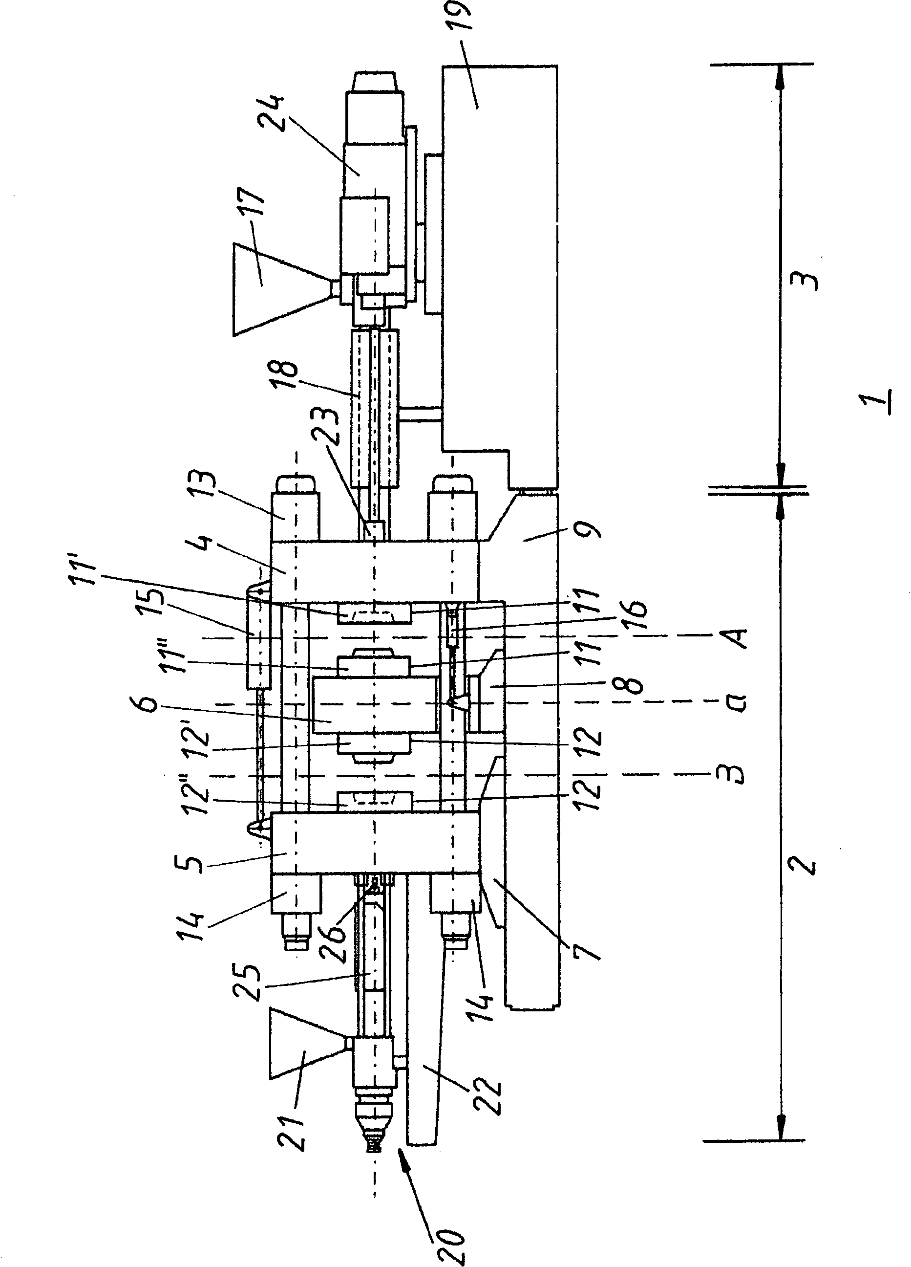
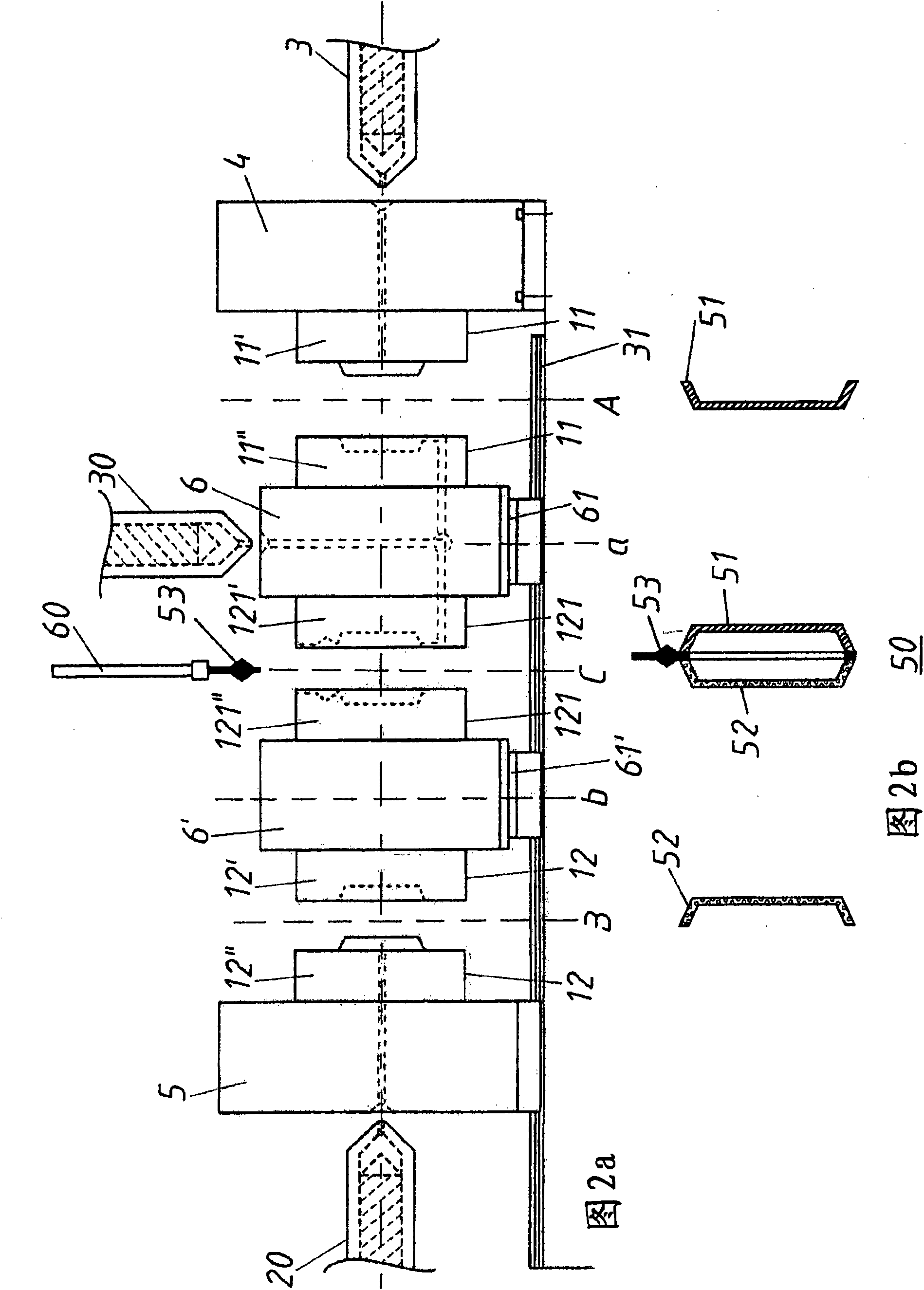
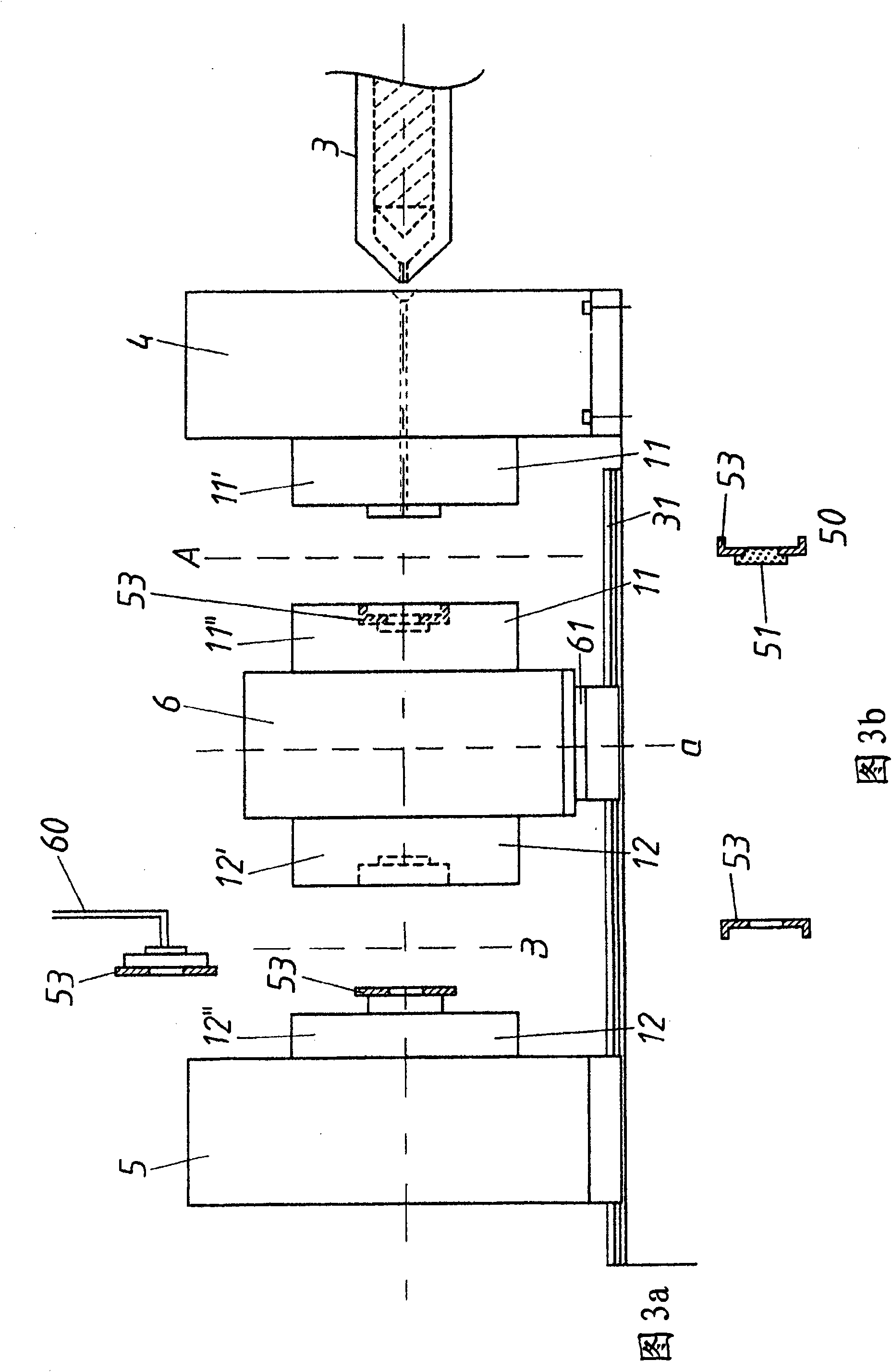
[0029] exist figure 1 An injection molding machine 1 is shown in , which can be used for the method according to the invention. The injection molding machine 1 here has a clamping unit 2 and a plasticizing and injection unit 3 in a known manner. The mold clamping unit 2 includes a fixed mold base plate 4 fixedly arranged on a frame 9 . Also be provided with a movable mold base plate 5 in addition, this mold base plate is in a for example in Figure 2a The slide block 7 on the slide rail 31 shown in the figure can move linearly along the column 10. The movement of the movable base plate 5 is carried out by means of travel cylinders 16 with piston-cylinder units away from and towards the movable (fixed) cover plate 4 . In order to fix the movable mold base plate 5 in the desired position, a locking mechanism 14 is provided on the column 10 , which secures the mold base plate 5 to the column 10 with a positive and / or frictional fit. superior. Furthermore, a turntable plate 6...


PUM


Abstract

The present invention relates to a method for producing a composite or farrago structure including at least one thermoplastic plastic component, wherein the method adopts an injection molding machine (1) having at least one rotating plate (6, 6').

Description

technical field [0001] The invention relates to a method for producing composite or hybrid structures comprising at least one thermoplastic component. Background technique [0002] According to the prior art, various methods are known for producing composite structures or composite materials, but also for producing hybrid structures. In composite materials, various materials are connected by material bonding or form locking or a combination of both. For example, there may be mentioned fiber composite materials in which fiber woven or knitted fabrics are mixed with plastics in order to obtain, as the end result, a composite structure which has improved properties. Systems with different technologies are combined in a hybrid structure. The hybrid structures are very often plastic / metal hybrids, in which the advantages of plastic and metal materials are combined. [0003] The methods known from the prior art for producing composite or hybrid structures are mostly multi-step,...

Claims


Application Information

Patent Timeline
IPC IPC(8): B29C45/06B29C45/14
CPCB29C45/14631B29C2045/1673B29C45/1418B29C45/0062B29C45/32B29C2045/14213B29C45/1679B29C45/1628B29C45/1671B29C2045/14877
Inventor P·艾格H·纳德希恩G·施泰因比希勒H·蔡德尔霍费尔
Owner ENGEL AUSTRIA
Learn More