
Automotive climate system

A technology for automotive air-conditioning systems and cabins, which is applied to vehicle components, refrigeration safety arrangements, refrigerators, etc., and can solve the problem that the speed of the compressor cannot be changed.

Active Publication Date: 2010-12-01
FORD GLOBAL TECH LLC
View PDF4 Cites 13 Cited by
  • Summary
  • Abstract
  • Description
  • Claims
  • Application Information

AI Technical Summary

Problems solved by technology

That is, the speed of the compressor cannot be changed

Method used

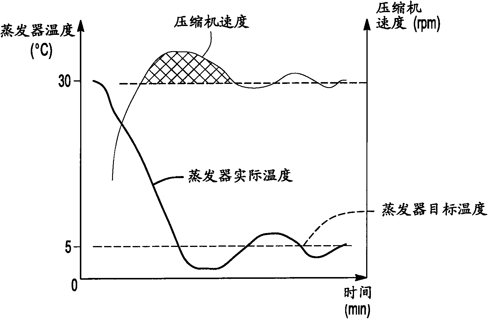
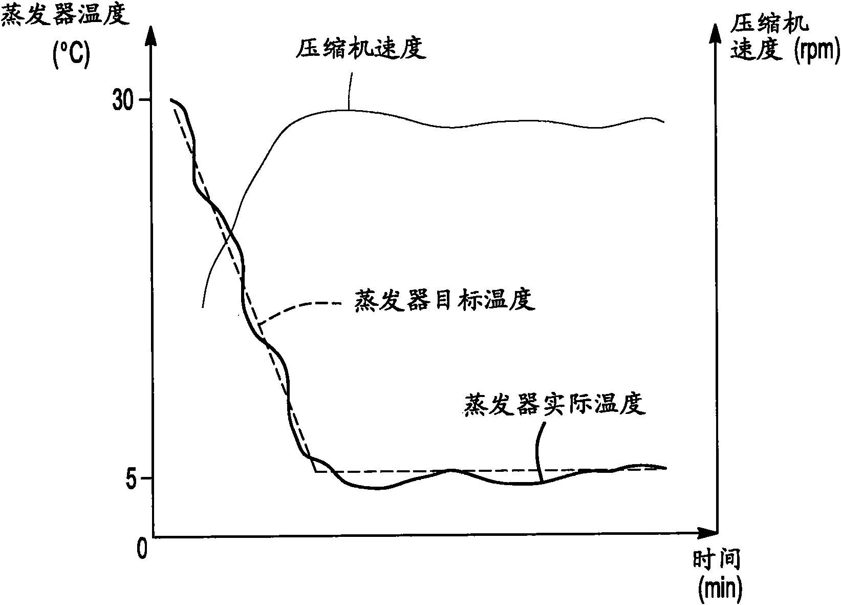

Image

  • Automotive climate system
  • Automotive climate system
  • Automotive climate system

Examples


Embodiment Construction

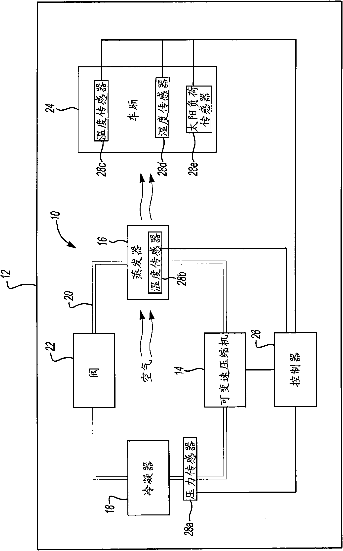
[0010] now refer to figure 1 An embodiment of an air conditioning system 10 for a motor vehicle 12 includes a variable speed compressor (eg, an electric compressor) 14 , an evaporator 16 , a condenser 18 , a fluid circuit 20 and a valve 22 . As is known to those of ordinary skill, the coolant is circulated through a fluid circuit 20 that fluidly connects the variable speed compressor 14 , the evaporator 16 and the condenser 18 . Valve 22 is actuatable to control the flow of coolant through fluid circuit 20 . The coolant cools the air passing through the evaporator 16 . This air may be used to cool the cabin 24 of the motor vehicle 12 .

[0011] Air conditioning system 10 also includes a controller 26 and one or more sensors 28n (28a-28e). exist figure 1 In the preferred embodiment, sensor 28a senses the pressure in fluid circuit 20 between variable speed compressor 14 and condenser 18 . The sensor 28b senses the temperature of the evaporator 16 . Sensors 28c-28e sense te...


PUM


Abstract

An automotive climate control system includes an evaporator, a variable speed compressor and a controller. The controller is configured to periodically alter a previous target evaporator temperature at a selected rate to generate a current target evaporator temperature, select a target compressor speed based on a difference between an actual evaporator temperature and the current target evaporator temperature, and command the compressor to operate at the target compressor speed.

Description

technical field [0001] The invention relates to an automobile air conditioning system. Background technique [0002] Automotive air conditioning systems may include a compressor that pressurizes and moves refrigerant passing through an evaporator. Such compressors operate to meet the cooling demands of the cabin. These compressors operate in either full-on mode or full-off mode. That is, the speed of the compressor cannot be changed. Other compressors (eg, electric air conditioning compressors) may run at varying speeds. Contents of the invention [0003] In a particular embodiment, an automotive air conditioning system includes an evaporator, a variable speed compressor, and a controller. The controller is configured to periodically vary the previous evaporator target temperature at a selected rate to produce a current evaporator target temperature, select a compressor target speed based on the difference between the actual evaporator temperature and the current evapo...

Claims


Application Information

Patent Timeline
Patent Type & Authority Applications(China)
IPC IPC(8): F25B49/02
CPCB60H2001/3263B60H1/3211F25B2600/0253F25B2700/2117F25B49/022B60H2001/3251F25B2700/195F25B2700/2104B60H2001/3272
Inventor 苏珊·丽贝卡·齐卡内克威廉·大卫·特莱汉保罗·斯蒂芬·布赖恩大卫·杰森·麦克
Owner FORD GLOBAL TECH LLC
Learn More