Single board wireless debugging method and device

A debugging method and single-board technology, applied in the field of communication, can solve problems such as complex operation, unfavorable troubleshooting, and low efficiency, and achieve the effects of improving work efficiency, facilitating fault location, and convenient switching and debugging

Inactive Publication Date: 2014-12-10
ZTE CORP
View PDF5 Cites 0 Cited by
  • Summary
  • Abstract
  • Description
  • Claims
  • Application Information

AI Technical Summary

Problems solved by technology

[0004] The main purpose of the present invention is to provide a single-board wireless debugging method and device, to at least solve the problems that the single-board debugging method in the prior art is not conducive to troubleshooting, complicated operation, and low efficiency

Method used


Image

  • Single board wireless debugging method and device
  • Single board wireless debugging method and device
  • Single board wireless debugging method and device

Examples


Embodiment Construction

[0027] Hereinafter, the present invention will be described in detail with reference to the drawings and examples. It should be noted that, in the case of no conflict, the embodiments in the present application and the features in the embodiments can be combined with each other.

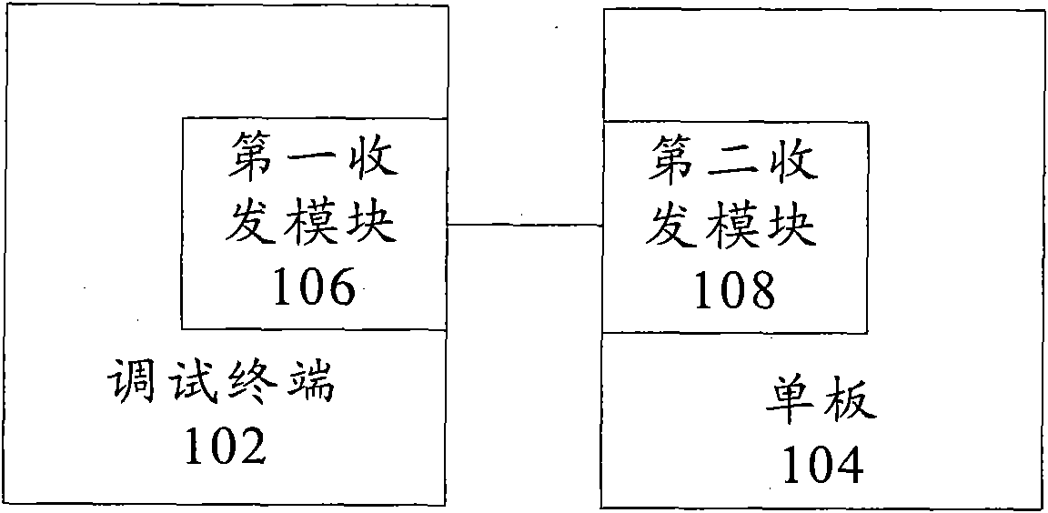
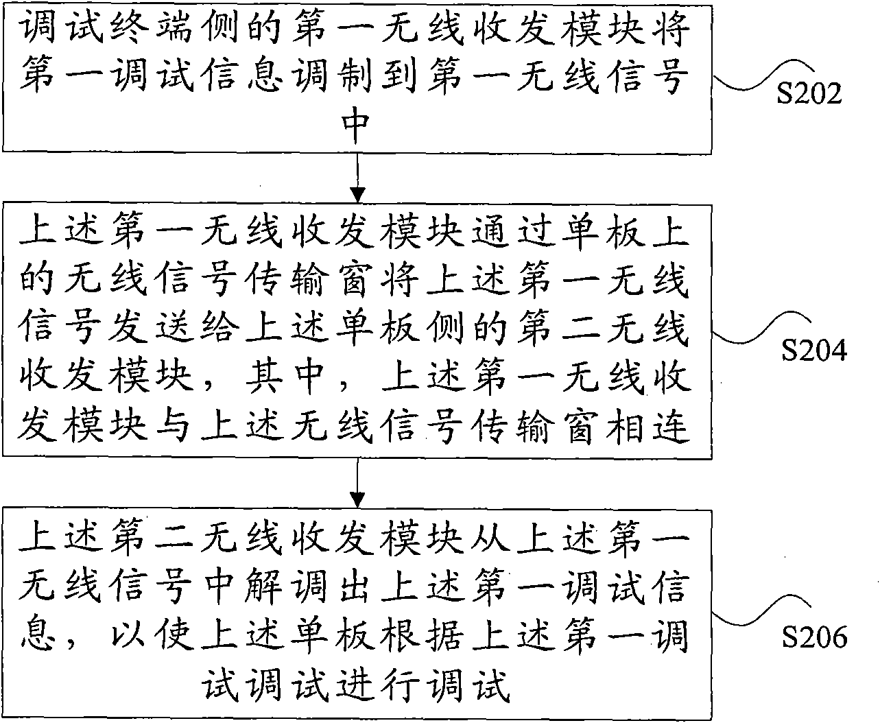
[0028] figure 1 is a schematic diagram of a debugging system including a single board and a debugging terminal according to an embodiment of the present invention. Such as figure 1 As shown, the above debugging system includes: a debugging terminal 102 and a single board 104 to be debugged, wherein the debugging terminal 102 may be a computer. The first transceiver module 106 on the debugging terminal 102 side is connected to the second transceiver module 108 on the board side 104 for transmitting debugging signals. The method for wirelessly debugging a single board will be specifically described below with reference to the accompanying drawings.

[0029] figure 2 It is a flowchart of a wireles...


PUM


Abstract

A wireless debugging method and device for a single board are disclosed by the present invention, wherein, the wireless debugging method for the single board includes the following steps: a first wireless receiving and transmitting module on a debugging terminal side modulates first debugging information to a first wireless signal (S202); the first wireless receiving and transmitting module transmits the first wireless signal to a second wireless receiving and transmitting module on the single board side through a wireless signal transmitting window on the single board, and wherein the first wireless receiving and transmitting module is connected with the wireless signal transmitting window (S204); the second wireless receiving and transmitting module demodulates the first debugging information from the first wireless signal, therefore the single board is debugged according to the first debugging information (S206). The invention solves the problem that the single board debugging method is not beneficial to removing faults and has complicated operation and low efficiency in the prior art, and is convenient to locate faults on engineering site.

Description

technical field [0001] The present invention relates to the communication field, in particular to a single board wireless debugging method and device. Background technique [0002] In communication equipment, the most commonly used interface for debugging boards is the RS-232 serial port, which is usually in the form of a pin (which can be understood as a socket), and the serial port cable needs to be inserted into the board for serial port connection. If the board is inserted into the device frame, the serial port cable cannot be plugged directly (this is because the frame and the panel are blocked, and you cannot reach in to plug in the wire), you need to pull the board out of the frame before plugging it in. Unplug the serial port cable, which will cause two problems: first, if the board fails during operation, you need to pull the board out of the chassis to plug in the serial port cable for debugging and troubleshooting, which will cause the board to be powered off , i...

Claims


Application Information

Patent Timeline
Patent Type & Authority Patents(China)
IPC IPC(8): H04W24/04
CPCH04W24/00G01R31/308
Inventor 叶位彬
Owner ZTE CORP
Why Eureka
Try Eureka