
Method for diagnosing a state in a vehicle, and diagnostic testing device

a technology for diagnosing a state and a vehicle, which is applied in the direction of digital transmission, instruments, data switching networks, etc., can solve the problems of unintentional discharge of the electrical system battery, higher power consumption, and inability to ascertain, so as to achieve the effect of higher power consumption

Active Publication Date: 2017-02-23
ROBERT BOSCH GMBH
View PDF1 Cites 5 Cited by
  • Summary
  • Abstract
  • Description
  • Claims
  • Application Information

AI Technical Summary

Benefits of technology

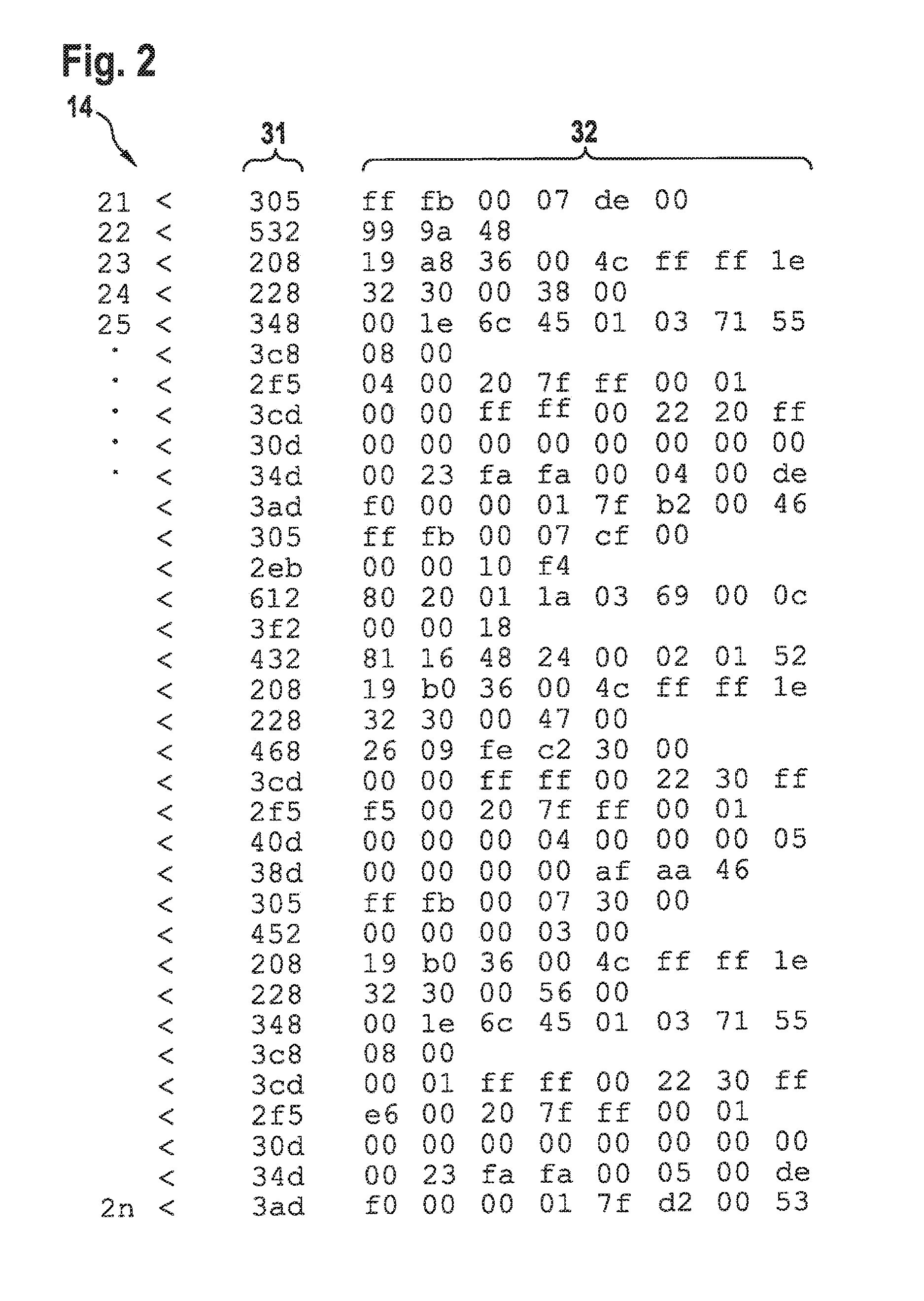
The present invention provides a method and device for diagnosing faults in a vehicle's garage. Unlike previous methods, which involved disconnecting electrical circuits and extracting fuses, the present invention uses a permanent scanning function of the vehicle's CAN communications bus to monitor its traffic. The device filters out unnecessary messages from control units and can identify unintended switching-on of control units, which leads to higher power consumption. The method is faster, more accurate, reliable, and eliminates the need for garage personnel to be present. The device can display the data content of detected CAN messages on a screen, making it easier to diagnose and localize faults. Overall, the present invention increases the throughput of the garage, saves assembly time, and positively impacts the customer's experience.

Problems solved by technology

A frequent case of a fault in motor vehicles is the discharging of the electrical system battery.
Although the vehicle is in a rest state (that is, in particular, the ignition is switched off and the vehicle is locked), defective attachment parts in vehicle systems, defective control units (ECUs), flawed software or incompatible hardware states may activate individual control units.
Then, activated control units often send messages continually onto the vehicle communications bus (CAN communications bus) and unintentionally discharge the electrical system battery due to a high power consumption.
Until now, it has not been possible to ascertain, using a diagnostic testing device, the initial fault location for an unwanted activation of a control unit and the accompanying discharge of the battery.
Depending on the manufacturer, it is often desired that individual control units be switched on at specific times. This behavior may be filtered out by the diagnostic testing device, in order to identify instances of unintended switching-on of control units, which result in higher power consumption.

Method used


Image

  • Method for diagnosing a state in a vehicle, and diagnostic testing device
  • Method for diagnosing a state in a vehicle, and diagnostic testing device
  • Method for diagnosing a state in a vehicle, and diagnostic testing device

Examples


Embodiment Construction

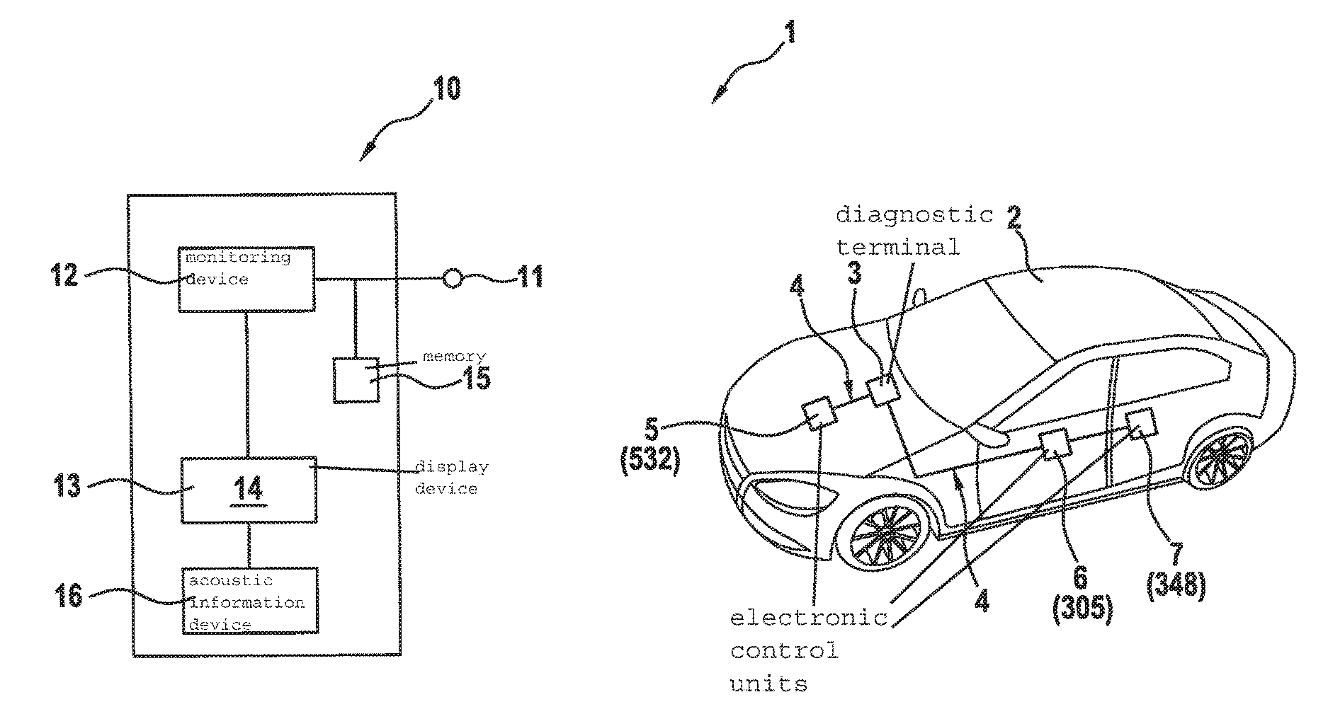
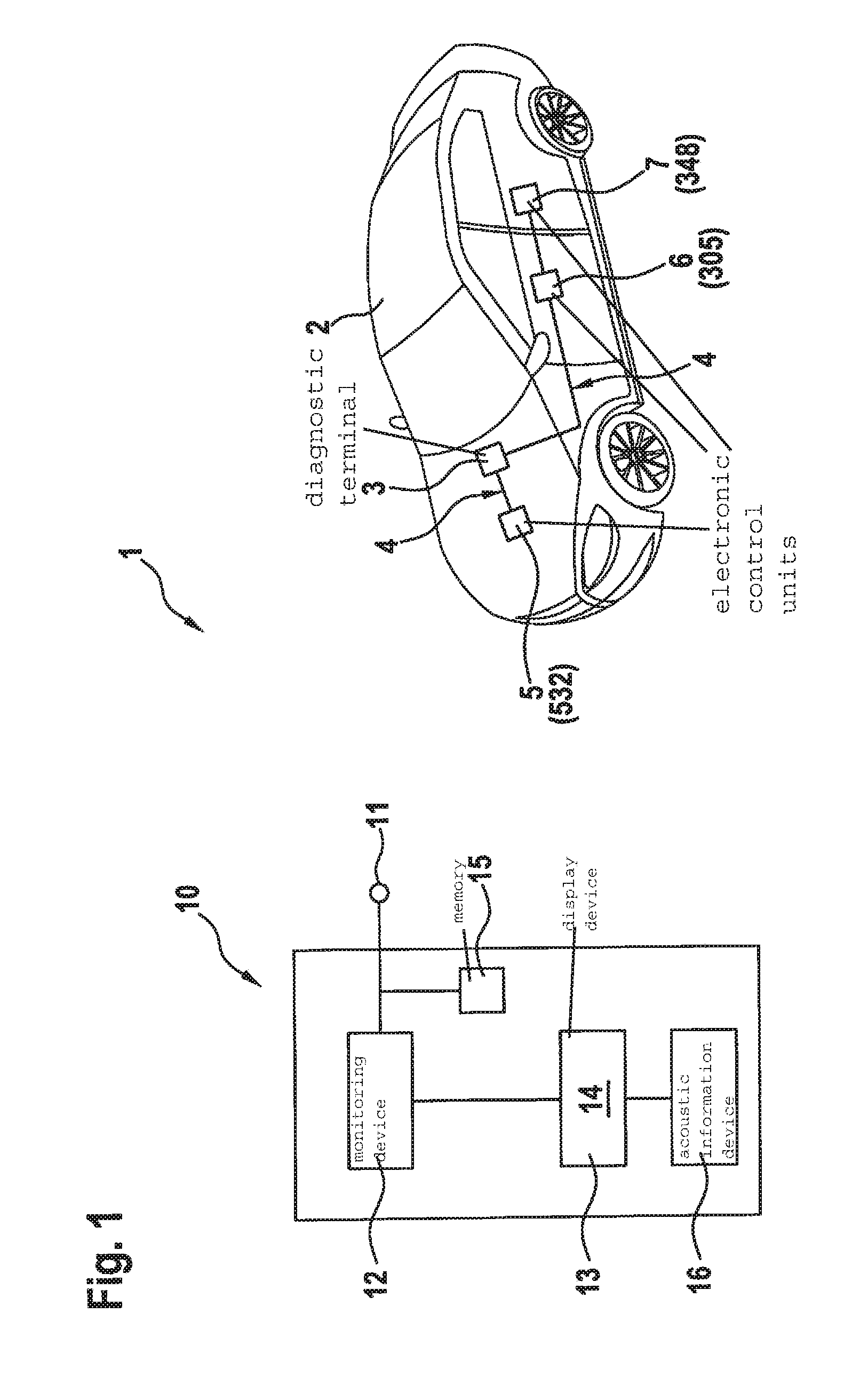
[0023]FIG. 1 shows a schematic view of an exemplary embodiment of a set-up 1 including a diagnostic testing device 10 for diagnosing a state in a vehicle 2, according to an exemplary embodiment of the present invention. Vehicle 2 includes a CAN communications bus 4, as is normally used in motor vehicles, to which electronic control units (ECUs) of vehicle 2 are connected. By way of example, control units 5, 6, 7 are displayed here in the form of central electronics 5, a driver's-side door control device 6 and a rear passenger-side door control device 7. In practice, other and / or further electronic control units are also connected to CAN communications bus 4 (in the following, abbreviated as: CAN bus).

[0024]Diagnostic testing device 10 is coupled to at least one diagnostic terminal 3 of vehicle 2 via a terminal 11; the at least one diagnostic terminal being able to be coupled, in turn, to CAN bus 4. The coupling may be carried out directly, or indirectly via other components. A wired...


PUM


Abstract

A method for diagnosing a state in a vehicle, which has a CAN communications bus to which electronic control units of the vehicle are connected, includes providing a rest state of the vehicle; coupling a diagnostic testing device to at least one diagnostic terminal of the vehicle; monitoring of the CAN communications bus by the diagnostic testing device with regard to CAN messages sent out after entry into the rest state; detecting of a CAN message sent out on the CAN communications bus after entry into the rest state, and assigning of the detected CAN message to an electronic control unit sending out the CAN message; providing information regarding a chronological appearance of the detected CAN message in a series of CAN messages appearing on the CAN communications bus after entry into the rest state; and providing information for identifying the electronic control unit sending out the detected CAN message.

Description

FIELD[0001]The present invention relates to a method for diagnosing a state in a vehicle, as well as to a diagnostic testing device.BACKGROUND INFORMATION[0002]A communications bus, such as a CAN communications bus in a vehicle, is typically coupled to a plurality of electronic control units (ECUs), which perform various functions and each form a bus node. Thus, an ECU is provided for door control, for example; the closing and / or opening of the doors being able to be controlled and monitored by the ECU. A microcontroller of an ECU, for instance, of a door control system, receives, for example, via the CAN communications bus, a bus message that a window of the doors should be opened. As a result, the microcontroller executes a so-called task (an operation), which triggers a corresponding circuit to open the window.[0003]A frequent case of a fault in motor vehicles is the discharging of the electrical system battery. Although the vehicle is in a rest state (that is, in particular, the...

Claims


Application Information

Patent Timeline
IPC IPC(8): G07C5/08H04L12/40H04L12/64
CPCG07C5/0808H04L12/6418H04L2012/40215H04L2012/40273H04L12/40H04L12/40006
Inventor WOERZ, ANDREASTREIBER, KLAUSENGELHARDT, MATHIAS
Owner ROBERT BOSCH GMBH
Learn More