Clasp and accessory
A buckle and jewelry technology, applied in clothing, decorative chains, watch chains, etc., can solve problems such as string breakage, and achieve the effects of easy and easy installation and removal, firm connection, and safe installation and removal.
- Summary
- Abstract
- Description
- Claims
- Application Information
AI Technical Summary
Problems solved by technology
Method used
Image

Examples
no. 1 approach
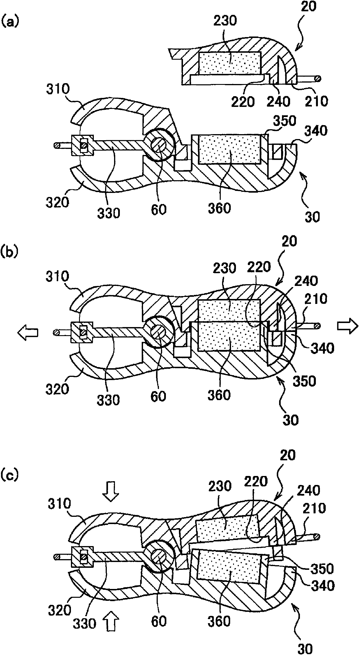
[0029] Below, refer to Figure 1 to Figure 3 The attached drawings describe in detail the structure of the buckle according to the first embodiment of the present invention.
[0030] figure 1 The external shape of the buckle 10 which concerns on 1st Embodiment of this invention is shown, (a) is a perspective view of the buckle 10, (b) is a longitudinal side view. The illustrated buckle 10 is roughly composed of a first housing 20 and a second housing 30 . The details of the first case 20 and the second case 30 will be described later, and these two cases are connected by magnetic force so that the user can easily detach them. And, one end of the first housing 20 is provided with a first connection end 40, and further, a second connection end 50 is provided at the end surface of the second housing 30, and accessories such as necklaces and bracelets using the clasp 10 are connected to these end connection.
[0031] The second housing 30 is mainly composed of a first componen...
no. 2 approach
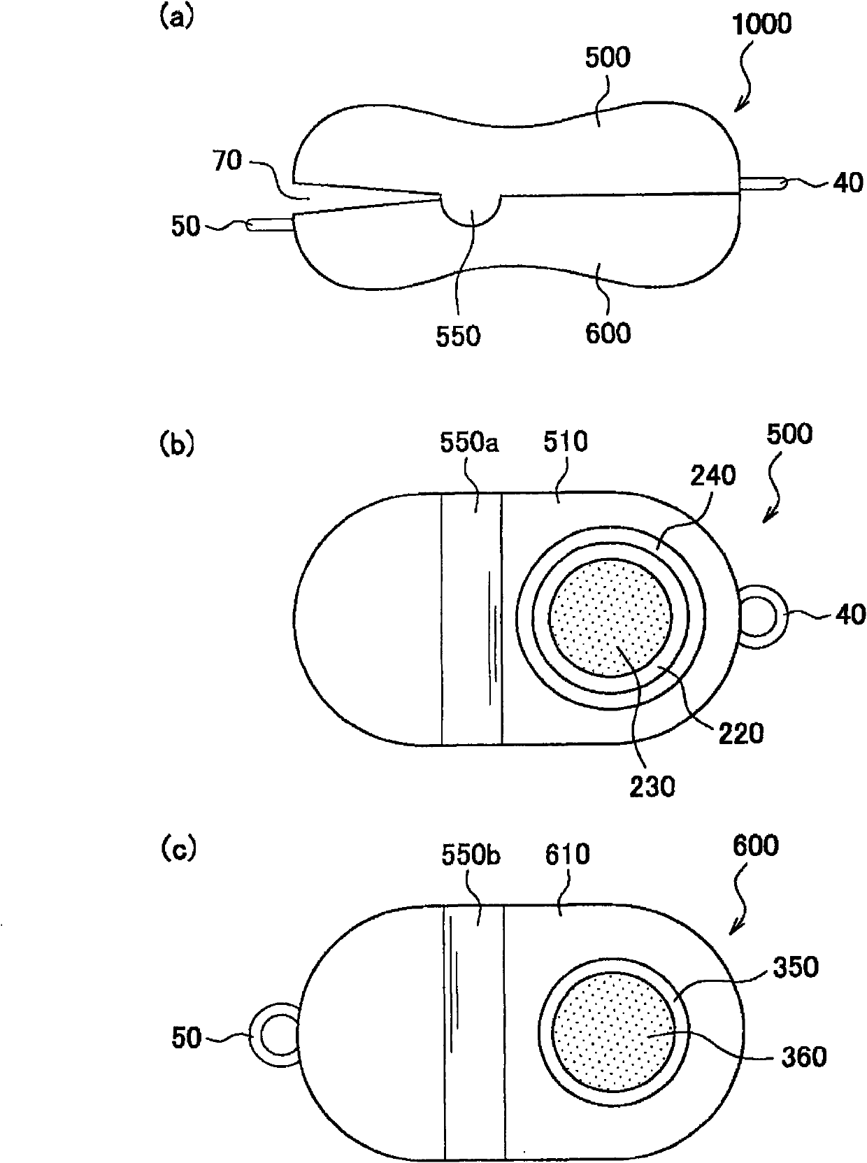
[0048] refer to Figure 4 The clasp 1000 which concerns on 2nd Embodiment of this invention is demonstrated. In addition, the same reference numerals are assigned to the same components as those of the buckle 10 of the first embodiment.
[0049] Figure 4 (a) is a longitudinal side view of the buckle 1000 of this embodiment. As shown in the figure, the buckle 1000 is mainly composed of a first shell 500 and a second shell 600 . Furthermore, both housings are connected by a connecting portion 550 .
[0050] Figure 4 (b) is the figure which looked at the 1st case 500 from the connection surface 510. As shown in FIG. The structures of the first flat portion 220 , the first magnet 230 and the protruding portion 240 are the same as those of the clasp 10 of the first embodiment, and the first housing 500 of this embodiment is provided with a first connection portion 550 a. The connecting portion is formed by a protruding portion extending along the lateral side of the first h...
no. 3 approach
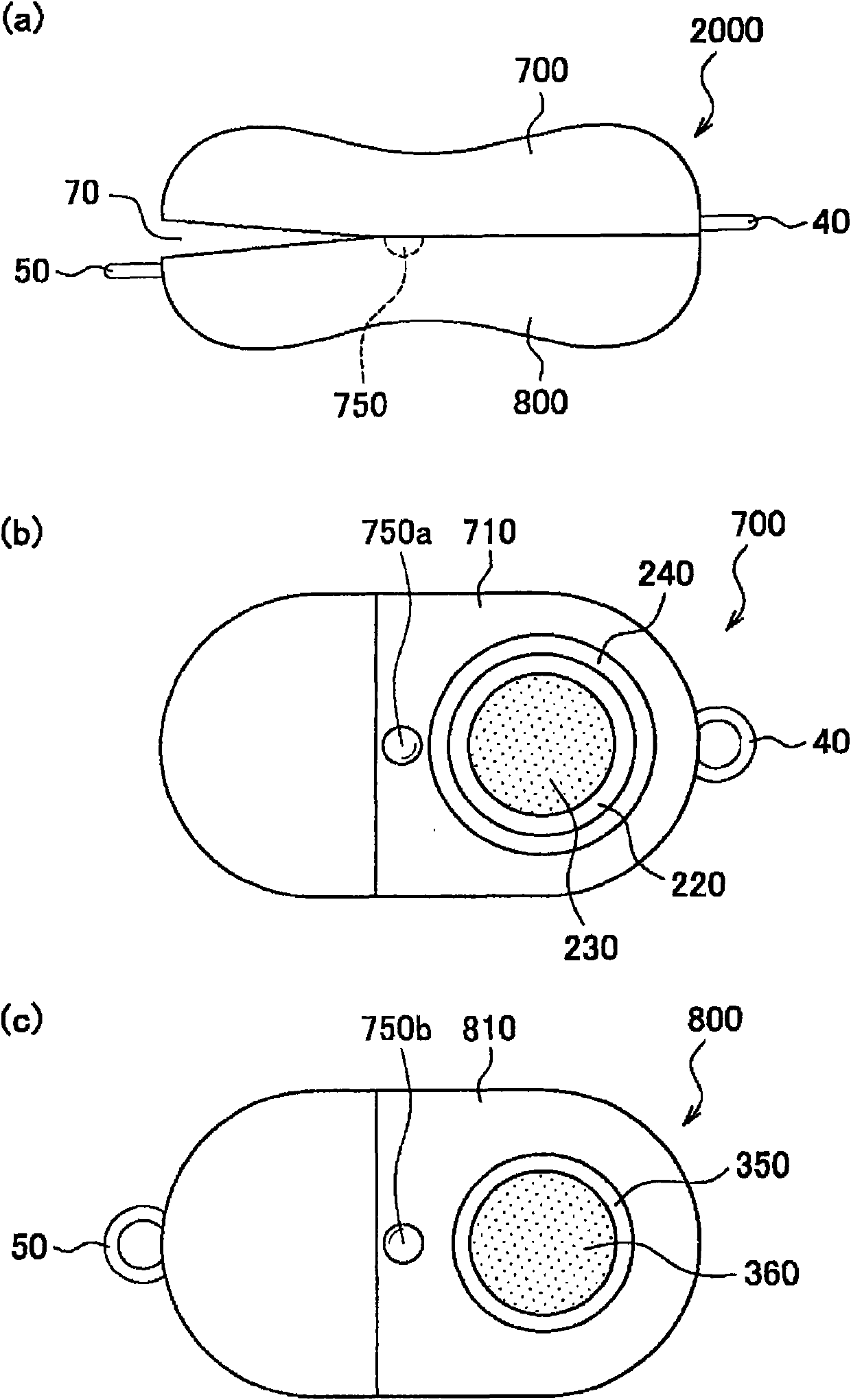
[0054] refer to Figure 5 The clasp 2000 which concerns on 3rd Embodiment of this invention is demonstrated. In addition, the same reference numerals are assigned to the same components as those of the buckle 10 of the first embodiment.
[0055] Figure 5 (a) is a longitudinal side view of the buckle 2000 of this embodiment. As shown in the figure, the buckle 2000 is mainly composed of a first housing 700 and a second housing 800 . Furthermore, both housings are connected by the connection part 750 . The structure of the connection portion 750 of this buckle 2000 is different from that of the buckle 1000 of the second embodiment. Therefore, only the connecting portion 750 will be described below.
[0056] Figure 5 (b) is the figure which looked at the 1st case 700 from the connection surface 710. As shown in FIG. The first housing 700 is provided with a first connection portion 750 a near the end of the connection surface 710 . The connecting portion is formed by a co...
PUM
 Abstract
Description
Claims
Application Information
 - R&D Engineer
- R&D Manager
- IP Professional
- Industry Leading Data Capabilities
- Powerful AI technology
- Patent DNA Extraction
Browse by: Latest US Patents, China's latest patents, Technical Efficacy Thesaurus, Application Domain, Technology Topic.
© 2024 PatSnap. All rights reserved.Legal|Privacy policy|Modern Slavery Act Transparency Statement|Sitemap