Water hammer eliminating device for mine drainage
A mine drainage and water hammer technology, which is applied in mining equipment, drainage, safety devices, etc., can solve the problems of water hammer hazards, pipe collapse, damage, etc., and achieve the effects of ensuring normal production, increasing stability, and increasing safety
- Summary
- Abstract
- Description
- Claims
- Application Information
AI Technical Summary
Problems solved by technology
Method used
Image
Examples
Embodiment 1
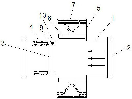
[0039] Such as figure 1 , 3 , 4, a water hammer elimination device for mine drainage; includes a pipe body 1, a flange 2; the end position of the pipe body 1 is provided with a flange 2, through which the pipe body 2 is arranged The body 1 is connected with the water pipe;
[0040] The upper and lower sides of the pipe body 1 are connected with a box body 5, and the side of the box body 5 close to the pipe body 1 is provided with a movable plate 6, and the movable plate 6 is connected with a buffer assembly 7. The component 7 is connected to the inner wall of the box body 5;
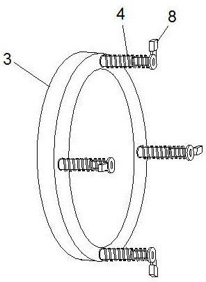
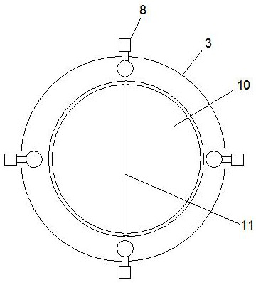
[0041] The inner wall of the pipe body 1 is provided with a piston ring 3, and the center of the piston ring 3 is provided with a rotating plate 10, the rotating plate 10 can rotate inside the piston ring 3, and one side of the piston ring 3 is connected with a plurality of elastic components 4, The other ends of the plurality of elastic components 4 are connected with connecting blocks 8 , and the ot...
Embodiment 2
[0043] Such as figure 2 , 5 As shown, on the basis of Embodiment 1, a hollow cavity 13 is provided between the inner wall and the outer wall of the piston ring 3, and the piston ring 3 is connected to the inner wall of the pipe body 1 through rubber ring sealing and sliding, and the cavity The inside of 13 is provided with a servo motor 9, the output shaft of the servo motor 9 runs through the inner wall of the piston ring 3, and the output shaft of the servo motor 9 is connected with a rotating shaft 11, and the rotating shaft 11 is connected with the rotating plate 10, and the rotating shaft 11 is arranged on the rotating The central position of the plate 10 drives the rotating plate 10 to rotate; the rotating plate 10 has a circular structure, and when the rotating plate 10 is closed with the piston ring 3, it is used to block water flow.
[0044] The elastic assembly 4 is evenly and symmetrically distributed on one side of the piston ring 3, the elastic assembly 4 includ...
Embodiment 3
[0048] Such as Figure 6 As shown, on the basis of Embodiment 1, the side of the movable plate 6 away from the pipe body 1 is connected with a fixed block 12, and the fixed block 12 is connected with the buffer assembly 7, and the buffer assembly 7 includes a connecting rod 71. Two connecting rods 71 are provided symmetrically, and one end of the two connecting rods 71 is connected to the fixed block 12 through a pin shaft, and the other ends of the two connecting rods 71 are connected with a moving ring 73, and the moving ring 73 is sleeved on the guide rod 72, and the moving ring 73 is slidably connected with the guide rod 72.
[0049] Described guide rod 72 is arranged on the inside of described box body 5 away from an end of movable plate 6, and the two ends of guide rod 72 are all connected with box body 5 inner walls, and described guide rod 72 is provided with chute far away from the side of movable plate 6 76 , the moving ring 73 is connected with a slider 75 ne...
PUM
 Abstract
Description
Claims
Application Information
 - R&D
- Intellectual Property
- Life Sciences
- Materials
- Tech Scout
- Unparalleled Data Quality
- Higher Quality Content
- 60% Fewer Hallucinations
Browse by: Latest US Patents, China's latest patents, Technical Efficacy Thesaurus, Application Domain, Technology Topic, Popular Technical Reports.
© 2025 PatSnap. All rights reserved.Legal|Privacy policy|Modern Slavery Act Transparency Statement|Sitemap|About US| Contact US: help@patsnap.com


