Vapor deposition apparatus and vapor deposition method

A vapor deposition and equipment technology, applied in the field of vapor deposition equipment, can solve the problems of reducing deposition rate and material efficiency, and achieve the effect of reducing vapor flow and reducing the difference in deposition direction

Inactive Publication Date: 2010-12-08
SONY CORP
View PDF9 Cites 6 Cited by
  • Summary
  • Abstract
  • Description
  • Claims
  • Application Information

AI Technical Summary

Problems solved by technology

However, when the angle of incidence of the vapor stream 64 on the substrate 66 is restricted in this manner, the deposition rate is reduced, reducing material efficiency.

Method used


Image

  • Vapor deposition apparatus and vapor deposition method
  • Vapor deposition apparatus and vapor deposition method
  • Vapor deposition apparatus and vapor deposition method

Examples


no. 1 example

[0033] (1) Structure of vapor deposition equipment

[0034] (2) Steps of vapor deposition method

[0035] (3) example

[0036] a. The cooling capacity of the substrate

[0037] b. Appearance and cross-sectional structure after deposition

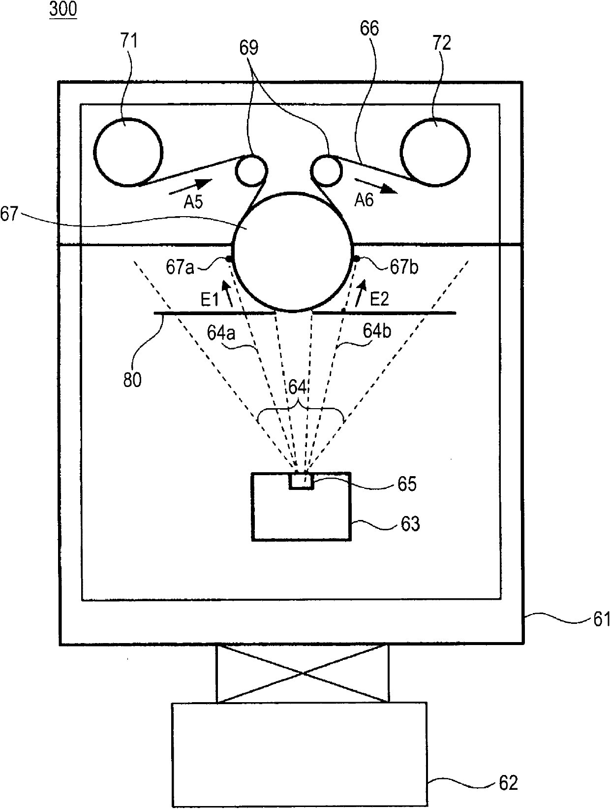
[0038] 2. The second embodiment of the vapor deposition method

[0039] 3. The second embodiment of vapor deposition equipment

[0040] 1. The first embodiment of vapor deposition equipment and vapor deposition method

[0041] (1) Structure of vapor deposition equipment

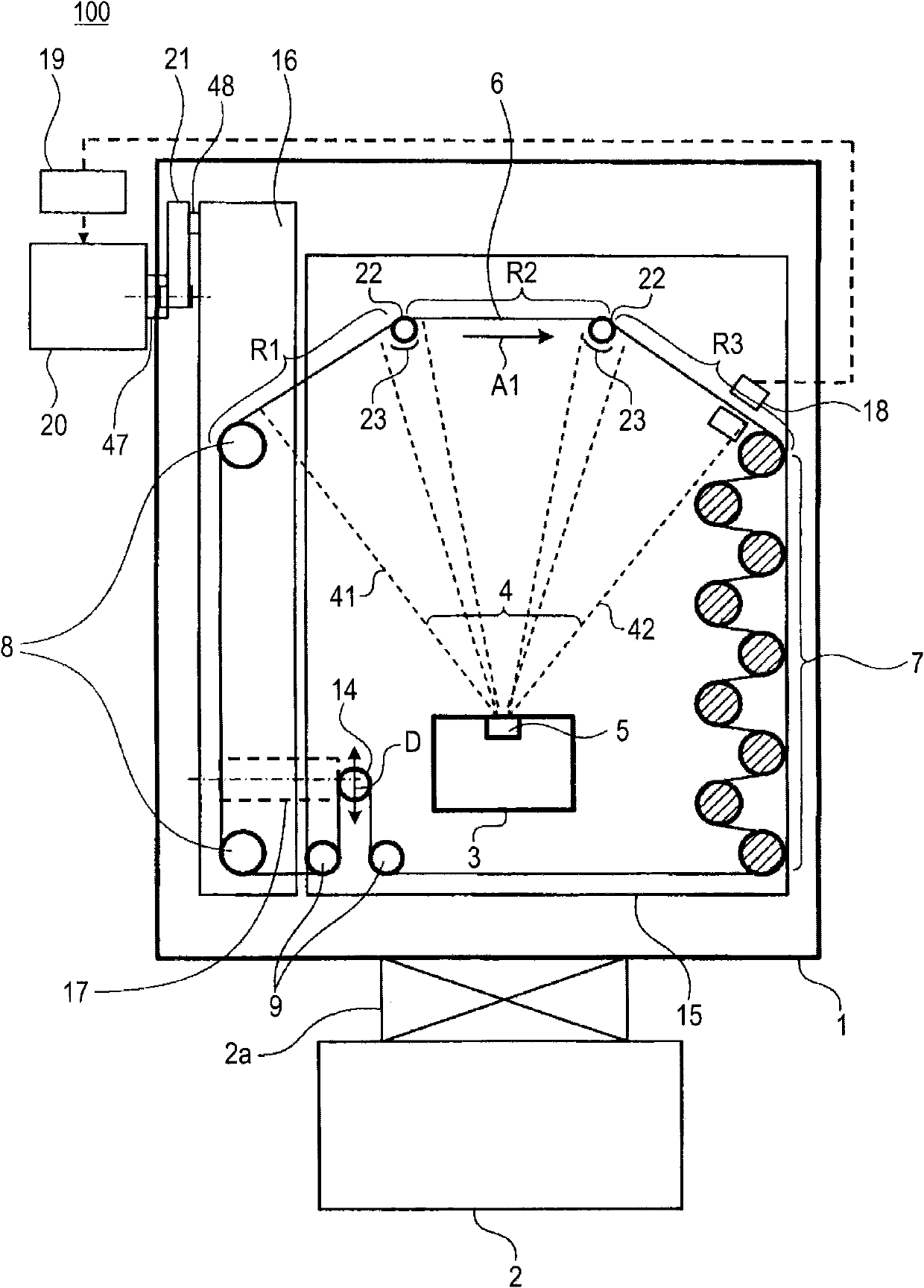
[0042] figure 1 is a schematic configuration diagram of the vapor deposition apparatus 100 according to the first embodiment. The vapor deposition apparatus 100 according to the embodiment has a vacuum tank 1 and a vacuum pump 2 that evacuates the inside of the vacuum tank 1 as an exhaust section. The vacuum tank 1 is evacuated to, for example, 10 by a vacuum pump 2 connected thereto via a valve 2a. -2 to 10 -4 Pa.

[0043] The rollers 22 define a concave travel...


PUM

PropertyMeasurementUnit
thicknessaaaaaaaaaa

Abstract

A vapor deposition apparatus includes: a vacuum tank; an exhaust section that performs vacuum exhaust in the vacuum tank; a vapor deposition source disposed in the vacuum tank to vaporize a deposition material; and a traveling path for allowing an elongated substrate on which the deposition material is deposited to travel along a concave path with respect to the vapor deposition source at least in a region opposing the vapor deposition source.

Description

technical field [0001] The present invention relates to a vapor deposition apparatus and a vapor deposition method for depositing a film on a long and narrow substrate. Background technique [0002] In the case of forming a thin film on a flexible substrate such as a plastic film or metal foil by vacuum deposition, a winding type vapor deposition apparatus has been used in the past. Figure 12 is a schematic configuration diagram showing the roll-to-roll vapor deposition apparatus 300 . [0003] The roll-to-roll type vapor deposition apparatus 300 according to the prior art has a vacuum tank 61 and a vacuum pump 62 that evacuates the inside of the vacuum tank 61 . Provided in the vacuum tank 61 are: cooling roller 67 which cools the substrate 66 along its periphery during vapor deposition; roller 71 which winds out the substrate 66 before vapor deposition; roller 72 which winds up the substrate 66 after vapor deposition ; and guide rollers 69 that guide the travel path of t...

Claims


Application Information

Patent Timeline
Patent Type & Authority Applications(China)
IPC IPC(8): C23C14/24
CPCC23C14/562C23C14/24C23C14/50
Inventor 阿部淳博
Owner SONY CORP
Why Eureka
Try Eureka