Interface device for host device, interface device for slave device, host device, slave device, communication system and interface voltage switching method
A technology of an accessory device and an interface device, which is applied in the field of interface circuits, and can solve problems such as only switching the voltage of the interface circuit
- Summary
- Abstract
- Description
- Claims
- Application Information
AI Technical Summary
Problems solved by technology
Method used
Image
Examples
no. 1 Embodiment approach
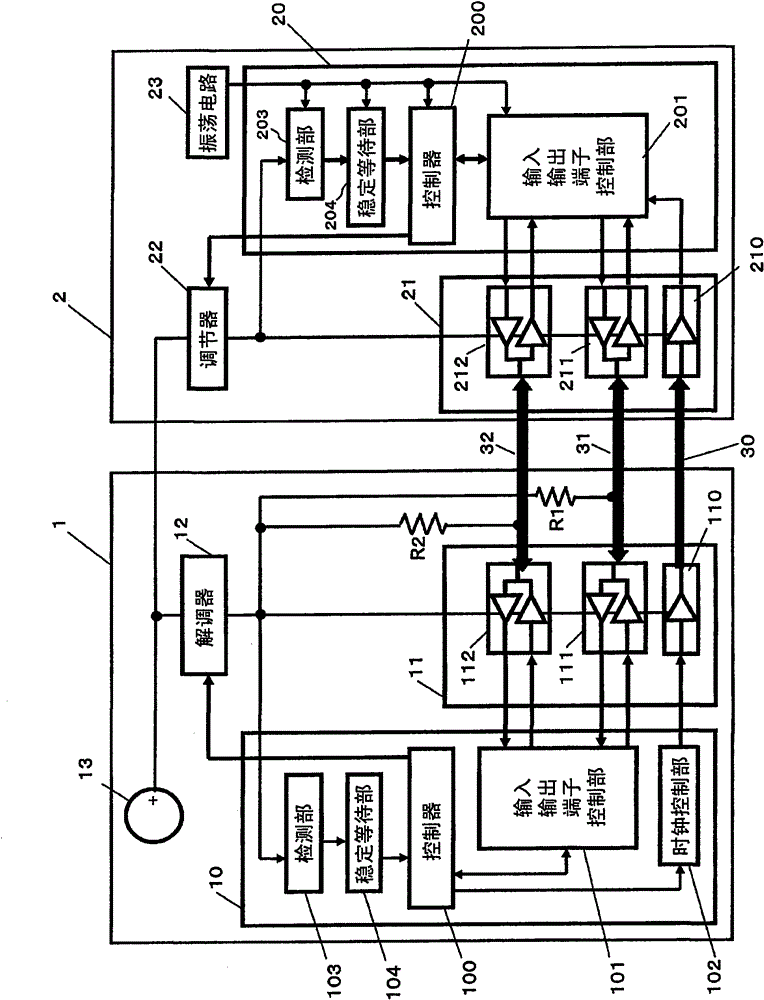
[0134] figure 1 It is a diagram showing the configuration of the communication system according to the first embodiment of the present invention.
[0135] Such as figure 1 As shown, the communication system according to this embodiment includes a main device 1 and an accessory device 2 . The master device 1 and the slave device 2 are connected by buses 30 to 32 .
[0136] The bus lines 31 and 32 are connected to an output voltage of a regulator described later via pull-up resistors R1 and R2.
[0137] The bus 30 is used for clock sending, the bus 31 is used for command sending and receiving, and the bus 32 is used for data sending and receiving.
[0138] Here, the command is an instruction from the master device 1 to perform register read / write processing, storage area read / write processing, or processing to acquire the status of the slave device 2 to the slave device 2 .
[0139] Although the command / data transmission and reception of the buses 31 and 32 are performed syn...
Embodiment 1
[0197] use Figure 3A An example (an example) of the communication system of the present embodiment described above will be described.
[0198] In this embodiment (hereinafter referred to as "Embodiment 1"), the first interface voltage is set to "V1" (for example, 3.3 [V]) and the second interface voltage is set to "V1" in the communication system. V2" (for example, 1.8 [V]), the case of switching the interface voltage from "V1" to "V2" will be described.
[0199] In addition, for the convenience of explanation, in Figure 3A The numbers (1) to (9) are assigned in the above, and the operation of the communication system in the first embodiment (processing (1) to (9)) will be described corresponding to the numbers.
[0200] Processing (1):
[0201] The master device 1 issues the command CMD, and then starts a voltage switching sequence (voltage switching process).
[0202] Processing (2):
[0203] The accessory device 2 returns a response to the main device 2 .
[0204] P...
no. 2 Embodiment approach
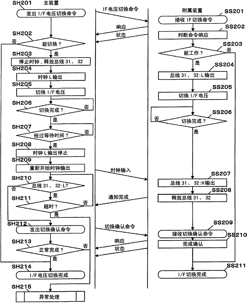
[0231] Next, use Figure 4 The flow chart of FIG. 2 describes the processing procedure for switching the interface voltage between the master device 1 and the slave device 2 of the communication system according to the second embodiment of the present invention.
[0232] In the communication system according to this embodiment, the input / output terminal 112 of the main device 1 and the input / output terminal 212 of the accessory device 2 may be open drain outputs. other components and figure 1 The descriptions are the same.
[0233]
[0234] Such as Figure 4 As shown, in the communication system according to the present embodiment, the slave device 2 operates in accordance with commands from the master device 1 . Therefore, when switching the interface voltage, first, the controller 100 of the master device 1 performs a process of issuing an I / F voltage switching command to the slave device 2 (SH401).
[0235] When the controller 200 of the accessory device 2 receives an...
PUM
 Abstract
Description
Claims
Application Information
 - R&D
- Intellectual Property
- Life Sciences
- Materials
- Tech Scout
- Unparalleled Data Quality
- Higher Quality Content
- 60% Fewer Hallucinations
Browse by: Latest US Patents, China's latest patents, Technical Efficacy Thesaurus, Application Domain, Technology Topic, Popular Technical Reports.
© 2025 PatSnap. All rights reserved.Legal|Privacy policy|Modern Slavery Act Transparency Statement|Sitemap|About US| Contact US: help@patsnap.com


