Centrifugal forming tool

A centrifugal molding and tooling technology, which is applied to the manufacturing tools, ceramic molding machines, ceramic molding cores, etc., can solve the problems of complex structure of automatic molding centrifugal devices, easy to produce interference phenomenon, inconvenient operation, etc., and achieve simple structure and low cost. , the effect of saving materials

Inactive Publication Date: 2010-12-15
湖南邱则有专利战略策划有限公司
View PDF1 Cites 1 Cited by
  • Summary
  • Abstract
  • Description
  • Claims
  • Application Information

AI Technical Summary

Problems solved by technology

[0006] However, the structure of this thin-walled cement pipe automatic forming centrifugal device is still relatively complicated. When installing and disassembling the forming mold in the rotating cylinder, it is necessary to remove the injection device first, and then install and fold the forming mold, which occupies a large working surface. Interference with components is easy to occur, and the operation is inconvenient

Method used


Image

  • Centrifugal forming tool
  • Centrifugal forming tool
  • Centrifugal forming tool

Examples


Embodiment Construction

[0108] The present invention will be further described below in conjunction with the accompanying drawings and embodiments.

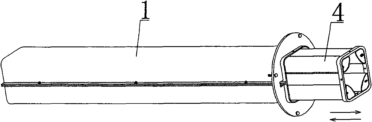
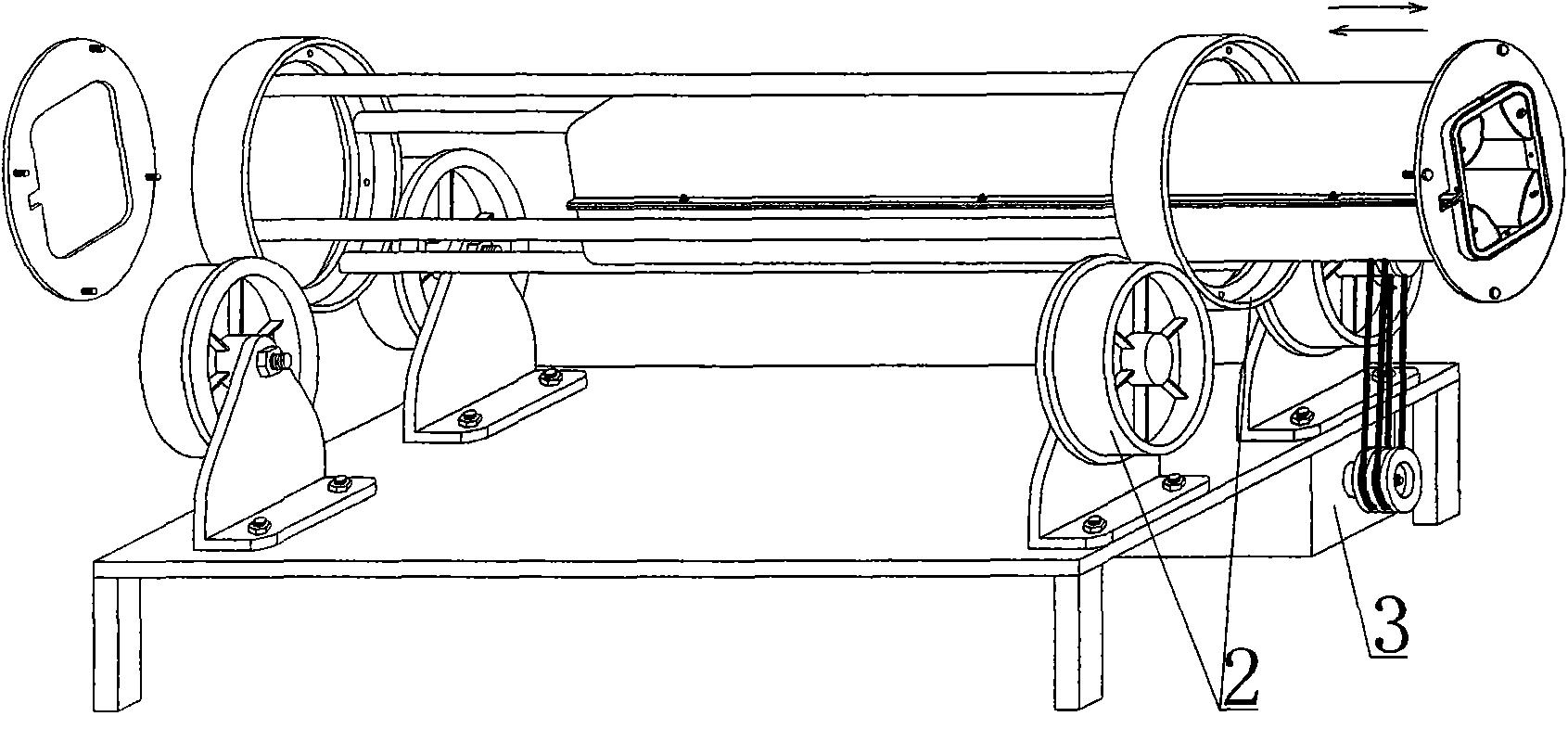
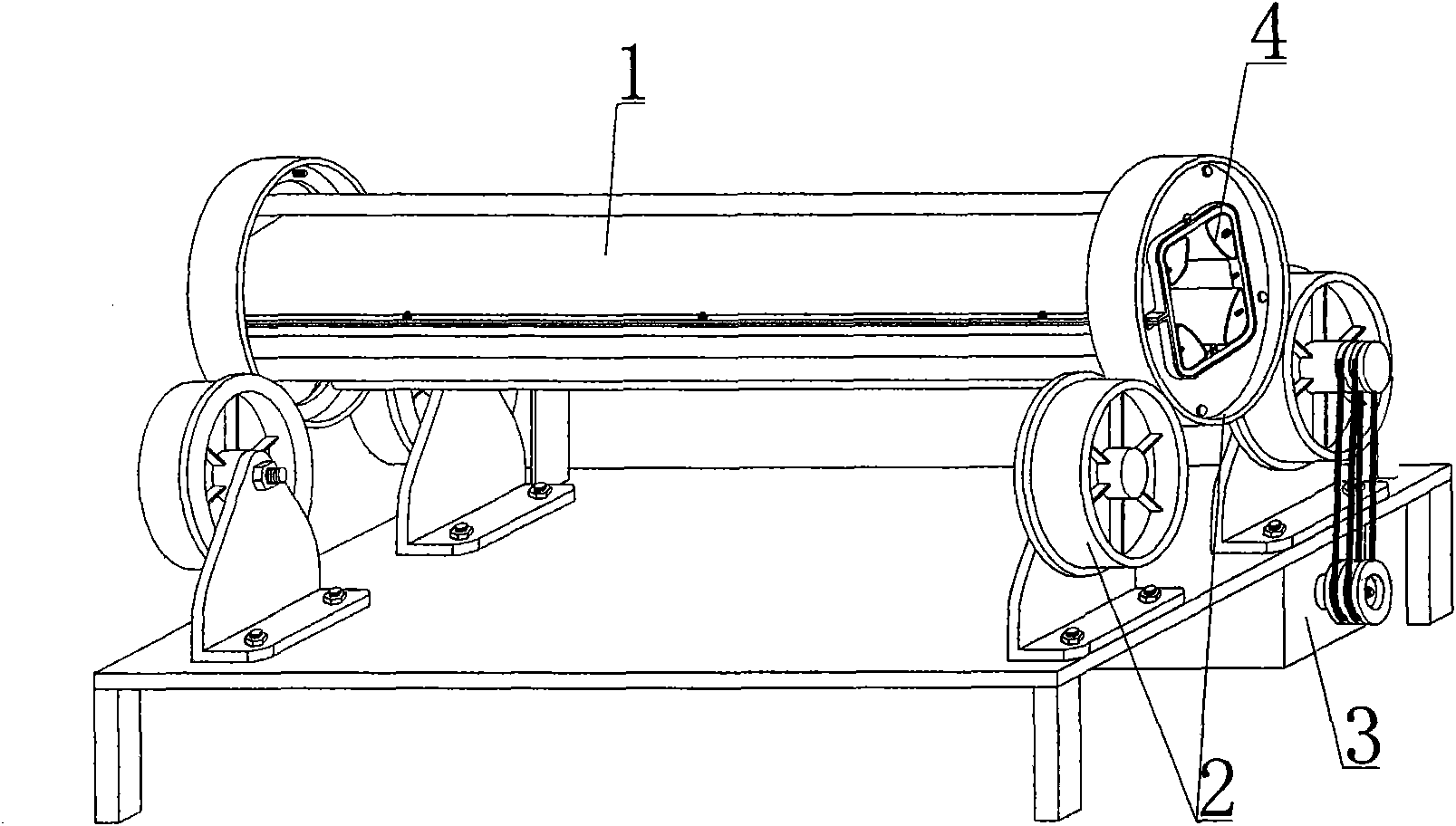
[0109] As shown in the accompanying drawings, the present invention includes a ring-shaped mold 1, a mold support 2, and a centrifugal drive member 3. It is characterized in that there is at least one core mold 4 that limits the internal shape of the product in the ring-shaped mold 1, and the ring-shaped mold 1 starts from the mold support. The end of 2 enters or disengages, and there are four core molds 4 in the annular tubular mold 1, and the core molds 4 are arranged at four corners in the annular tubular mold 1. In each accompanying drawing, 1 is an annular tubular mold, 2 is a mold support, 3 is a centrifugal drive member, and 4 is a mandrel. In the following accompanying drawings, those with the same number have the same description. Such as image 3 As shown, there are four core molds 4 that limit the internal shape of the product in the annular...


PUM


Abstract

The invention discloses a centrifugal forming tool. The centrifugal forming tool comprises a tubular mould (1), a mould bracket (2) and a centrifugal drive member (3), wherein at least one core mould (4) for limiting the inner shape of a product is arranged in the tubular mould (1); the tubular mould (1) enters or is separated from an end head of the mould bracket (2); and four core moulds (4) are arranged on the four corner parts in the tubular mould (1). The centrifugal forming tool is suitable for manufacturing the thin-walled pipes or thin-walled boxes, particularly the thin-walled pipes or thin-walled boxes with opening.

Description

[0001] This application is a divisional application of the invention patent application with the filing date of March 11, 2006, the application number of 2006100672786, and the title of "a centrifugal forming tool". (1) Technical field [0002] The invention relates to a centrifugal forming tool. (2) Background technology [0003] At present, the production of thin-walled cement pipes for domestic cast-in-place concrete hollow floors is usually manually operated, which has high labor intensity, low production efficiency, uneven wall thickness, poor product quality, and waste of production materials. In order to solve the current The technical problems existing in actual production, the patent No. ZL03211400.1, titled "a kind of centrifugal device for automatic forming of thin-walled cement pipes" solved the above problems well. This thin-walled cement pipe automatic forming centrifugal device includes a support base, a support roller, a pressure plate, a clamping bolt, a pre...

Claims


Application Information

Patent Timeline
Patent Type & Authority Applications(China)
IPC IPC(8): B28B21/30B28B21/80B28B21/82B28B21/88
Inventor 邱则有
Owner 湖南邱则有专利战略策划有限公司
Why Eureka
Try Eureka