Key end mill convenient to place

An end mill and key technology, applied in the field of machining tools, can solve the problems affecting the use effect of the key end mill, the wear of the cutter head of the key end mill, and the small size of the key end mill, so as to achieve good application prospects and improve Processing efficiency, the effect of increasing the processing range

Inactive Publication Date: 2018-01-05
张家港市锐正精密工具有限公司
View PDF0 Cites 0 Cited by
  • Summary
  • Abstract
  • Description
  • Claims
  • Application Information

AI Technical Summary

Problems solved by technology

[0003] The purpose of the present invention is to overcome the small size of the existing key end mills, which is easy to wear the cutter head of the key end mill during transportation or placement, which affects the use effect of the key end mill, and the shape of the cutter head single question

Method used


Image

  • Key end mill convenient to place
  • Key end mill convenient to place

Examples


Embodiment Construction

[0016] The present invention will be further described below in conjunction with the accompanying drawings.

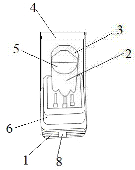
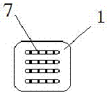
[0017] Such as figure 1 and figure 2 As shown, the easy-to-place key end mill of the present invention includes a placement base 1, a key end mill cutter column 2, a key end mill cutter head 3 and a transparent base cover 4, and the middle part of the placement base 1 There is a cylindrical groove 5 for placing the key end mill cutter column 2, the key end mill cutter column 2 is embedded in the cylindrical groove 5, and the key end mill cutter head 3 is located in the key end mill The top of the cutter column 2, and the two are integrally formed, the end of the key end mill cutter head 3 is in the shape of a semi-cone, and the two ends of the key end mill cutter head 3 in the shape of a semi-cone The side walls form the processing surfaces of the two end mills, and the edge of the upper surface of the base 1 shrinks inward to form a stepped edge 6 for inserting the...


PUM


Abstract

The invention discloses a key end mill that is easy to place. The middle part of the base is provided with a cylindrical groove for placing the key end mill cutter column, so as to ensure that the key end mill cutter column is placed independently and stably. It is equipped with a transparent base cover, which is convenient for uniform stacking and batch transportation, and does not damage the key end mill itself. The two side walls of the semi-conical shape at the end of the key end mill head form the processing of two end mills. Surface, increase the processing range of the key end mill head, improve the key processing efficiency, simple structure, easy to implement, and has a good application prospect.

Description

technical field [0001] The invention relates to the technical field of machining tools, in particular to a key end mill that is easy to place. Background technique [0002] Key end mills are common tools used to process keys. Due to the small size of the key end mill, it is not convenient to place, and it is easy to dump. During transportation or placement, it is easy to wear the head of the key end mill, which affects the use effect of the key end mill. Moreover, the existing key end milling cutter has a single shape of the cutter head and can only process one shape. When processing keys of different shapes, the key end milling cutter needs to be replaced, which affects the key processing efficiency. Contents of the invention [0003] The purpose of the present invention is to overcome the small size of the existing key end mills, which is easy to wear the cutter head of the key end mill during transportation or placement, which affects the use effect of the key end mill...

Claims


Application Information

Patent Timeline
Patent Type & Authority Applications(China)
IPC IPC(8): B23C5/10
Inventor 钱洪良
Owner 张家港市锐正精密工具有限公司
Why Eureka
Try Eureka