Fork frame vertical plate type bridge expansion joint connecting device

A technology for connecting devices and expansion joints, applied in the direction of bridges, bridge parts, bridge construction, etc., can solve problems such as increased cost, corrosion, and upper and lower deformation of the main steel plate.

Inactive Publication Date: 2021-10-01
王勇
View PDF1 Cites 0 Cited by
  • Summary
  • Abstract
  • Description
  • Claims
  • Application Information

AI Technical Summary

Problems solved by technology

[0004] Although this solution can prevent potential safety hazards, there are still shortcomings. First, the main steel plate will still be deformed up and down; It is easy to

Method used


Image

  • Fork frame vertical plate type bridge expansion joint connecting device
  • Fork frame vertical plate type bridge expansion joint connecting device
  • Fork frame vertical plate type bridge expansion joint connecting device

Examples


Embodiment 1

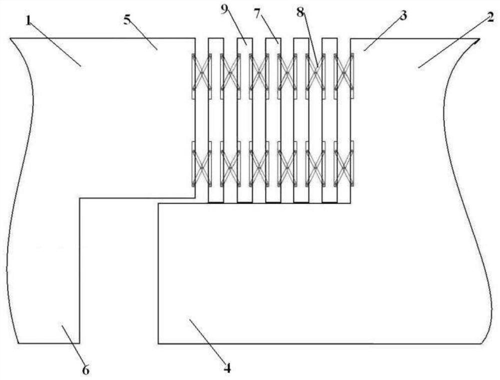
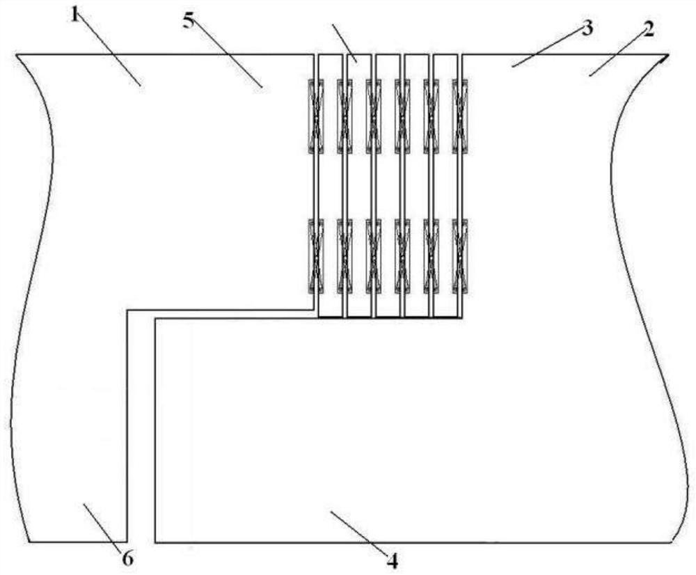
[0044] As shown in the figure, a fork vertical plate type bridge expansion joint connection device is made, including the left bridge body 1 and the right bridge body 2 that form the expansion joint, and the side of the expansion joint of the right bridge body 2 is a double-stage ladder that is placed upright structure, the two-stage ladder is called the right side body 3 and the platform body 4 respectively, the right side body 3 is generated above the platform body 4 and dislocated to the right; the side of the expansion joint of the left bridge body 1 is an inverted double-stage Ladder structure, the two-stage ladder is respectively called the left body 5 and the pituitary body 6, and the pituitary body 6 is generated under the left body body 5 and dislocated to the left; the pituitary body 6 is correspondingly isolated from the platform body 4, and the left side body 6 The side body 5 is suspended on the platform body 4 and is correspondingly isolated from the right side bo...

Embodiment 2

[0053] On the basis of Embodiment 1, a cover plate 27 is also provided above the left bridge body 1 and the right bridge body 2, and the cover plate 27 includes a flat plate portion 28 and an acute angle plate portion 29, wherein the flat plate portion 28 is located in the middle of the cover plate 27, and the flat plate portion 28 is a flat plate whose upper and lower surfaces are parallel to each other. The acute angle plate portion 29 is located on both sides of the flat plate portion 28 on the cover plate 27. The upper surface is inclined and intersects the acute angle plate with the lower surface; the flat part 28 of the cover plate 27 completely covers the several fork vertical plate chains 7 fixedly connected to the left side body 1 and the right side body 2 .

[0054] Further, the upper surfaces of the left bridge body 1 and the right bridge body 2 are respectively directly formed with first wave-shaped connecting grooves 30 protruding from the surface on the upper surf...

Embodiment 3

[0056] The construction method of the fork vertical plate type bridge expansion joint connection device includes the following steps:

[0057] (1) To make the bridge expansion joint partition surface, the sections of the left bridge body 1 and the right bridge body 2 constituting the expansion joints are both made into a double-stage ladder structure, wherein the expansion joint section of the left bridge body 1 is made into an inverted double-stage ladder structure, the two-stage ladder is called the left side body 5 and the pituitary body 6 respectively, and the pituitary body 6 is generated under the left side body 5 and dislocated to the left; the expansion joint section of the right bridge body 2 is made into an upright double The double-stage ladder is called the right side body 3 and the platform body 4 respectively, and the right side body 3 is generated above the platform body 4 and dislocated to the right; at the same time, the pituitary body 6 is corresponding to the...


PUM


Abstract

A fork frame vertical plate type bridge expansion joint connecting device belongs to the technical field of bridge engineering, and comprises a left bridge body and a right bridge body which form an expansion joint, the side face of the expansion joint of the right bridge body is provided with a right side body and a platform body, the side face of the expansion joint of the left bridge body is provided with a left side body and a vertical body, the left side body and the right side body are fixedly connected with a fork frame vertical plate chain, and the fork frame vertical plate chain is formed by connecting a plurality of fork frames and vertical plates end to end; the lower side face of the fork frame vertical plate chain is placed on the platform body, and the upper side face of the fork frame vertical plate chain is flush with the upper surface of the left side body and the upper surface of the right side body. Therefore, no matter how the expansion joint changes, a connecting device does not deform in the vertical direction when being loaded by a heavy object, and vehicles are not affected when passing through the expansion joint.

Description

technical field [0001] The invention relates to the technical field of bridge engineering, in particular to a fork stand vertical plate bridge expansion joint connection device. Background technique [0002] Expansion joints are an essential key structure in bridge construction. In order to meet the requirements of bridge deck deformation, expansion joints are usually set between two girder ends, between girder ends and abutments, or at the hinged position of the bridge. It is required that the expansion joints can freely expand and contract in two directions parallel to and perpendicular to the bridge axis, and are firm and reliable. The vehicles should run smoothly without sudden jumps and noises; they should be able to prevent rainwater and garbage from infiltrating and blocking; installation, inspection, and maintenance , Elimination of dirt should be simple and convenient. Where expansion joints are set, railings and bridge deck pavement must be disconnected. The role...

Claims


Application Information

Patent Timeline
IPC IPC(8): E01D19/06E01D19/08
CPCE01D19/06E01D19/083
Inventor 王勇
Owner 王勇
Why Eureka
Try Eureka