Method for detecting the position of a mobile switching element

A technology for shifting components and equipment, applied in the direction of mechanical equipment, components with teeth, transmission control, etc., can solve complex and other problems, and achieve the effects of reliable identification, simple electronic evaluation, and simple manufacturing

Active Publication Date: 2014-06-11
SCHAEFFLER TECH AG & CO KG
View PDF5 Cites 0 Cited by
  • Summary
  • Abstract
  • Description
  • Claims
  • Application Information

AI Technical Summary

Problems solved by technology

This requires complex and regular iterative calibration

Method used


Image

  • Method for detecting the position of a mobile switching element
  • Method for detecting the position of a mobile switching element
  • Method for detecting the position of a mobile switching element

Examples


Embodiment Construction

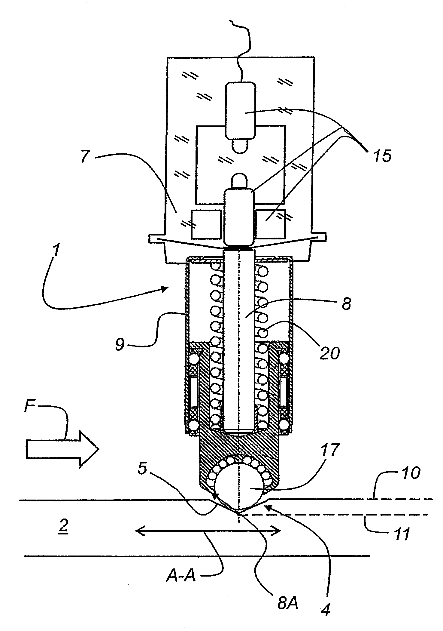
[0026] figure 1 A schematic diagram of a device 1 for detecting the position of a movable shifting or adjusting element 2 is shown. Shift or adjustment element 2 along the figure 1 Movement in the direction of movement shown by the double arrow A-A. The shifting or adjusting element has at least one stop 4 configured with a corresponding contour 5 . A device 1 for detecting the position of a movable shifting or adjusting element 2 is assigned to the shifting or adjusting element. The device 1 has a liftable pushbutton element 8 which carries a ball 17 on a front end 8A of the pushbutton element. The ball 17 engages in the contour 5 of the shifting or adjusting element 2 in a corresponding manner. The induction bolt 8 is pretensioned by means of a spring 20 . The induction bolt 8 itself moves inside the housing 9 . The posture of the sensing bolt 8 is detected by the sensor button 7 . For this purpose, the sensor button 7 includes a plurality of sensors 15 . The profile...


PUM


Abstract

The invention relates to a device (1) for detecting the position of a mobile switching element (2) which has at least one latching system (4) with a first contour (5) which has at least a first switching position at a top level (10), and at least a second switching position at a bottom level (11) of the latching system (4), wherein the latching system (4) is assigned a sensor probe (7) which has a spring-loaded probe element (8) which can move in a reciprocating fashion in a housing (9) and interacts with the latching system (4), and a sensor (15) is provided in the housing ((9), by which sensor (15) the position of the probe element (8) or of a component on which the probe element can act can be determined, and a position (P1, P2) of the switching element (2) can be detected therefrom, wherein the neutral position and the reverse gear position are determined by the extreme switching positions (10, 11).

Description

technical field [0001] The invention relates to a device for detecting the position of a movable shift element, in particular a shift rod or a shift shaft of a vehicle transmission. The shifting element has a stop arranged on or on the shifting element with at least one first contour. The detent occupies at least one shift position on the uppermost level and at least one shift position on the lowermost level. The stop is assigned a sensor button with a spring-loaded stop element that is movable up and down in the housing. Also arranged in the housing is a sensor which can determine the position of the liftable locking element and determine the position recognition therefrom. The spring-loaded locking element, which can be moved up and down, is usually a movable ball and cooperates with a stop on the shifting element. Background technique [0002] Laid-open document DE 10 2006 036 696 A1 discloses a sensor button for determining the attitude of at least one transmission co...

Claims


Application Information

Patent Timeline
Patent Type & Authority Patents(China)
IPC IPC(8): F16H59/70F16H63/38
CPCF16H2059/6823F16H59/70F16H63/38
Inventor 斯坦尼斯拉夫·马西尼托马斯·内迈尔
Owner SCHAEFFLER TECH AG & CO KG
Why Eureka
Try Eureka