Ribbed and grooved type wind turbine blade

A technology of wind turbine blades and grooves, which is applied in the field of wind turbine blades and ribbed and slotted wind turbine blades, which can solve the problems of high wind speed requirements for wind turbine startup, large fluctuations in power coefficient, and deterioration of lift-to-drag ratio. Achieve excellent output stability and stall characteristics, high bending resistance and fatigue damage resistance, and stable power output characteristics

Inactive Publication Date: 2015-06-03
INNER MONGOLIA UNIV OF TECH
View PDF5 Cites 0 Cited by
  • Summary
  • Abstract
  • Description
  • Claims
  • Application Information

AI Technical Summary

Problems solved by technology

[0004] 1. When operating at a low Reynolds number, the leading edge of the blade is more sensitive to roughness changes, and the lift-to-drag ratio deteriorates seriously, which greatly affects the stability of its power output
[0005] 2. In a wide tip speed ratio range, the power coefficient change is prone to large fluctuations, and stalling is prone to occur, and the power peak also has large fluctuations
[0006] 3. The start-up wind speed requirements of wind turbines are relatively high, which is not suitable for the utilization of low-speed wind energy resources
[0007] 4. The utilization rate of wind energy is low, resulting in a low effective utilization rate of wind resources in the wind power generation system as a whole
[0008] 5. The aerodynamic noise is large during operation, which affects the surrounding environment
[0009] 6. In order to pursue a high wind energy utilization rate, the blade airfoil design is thin, the bending resistance is poor, and it is easy to be damaged, resulting in frequent fatigue damage accidents caused by vibration during the operation of wind turbine equipment
[0010] The existence of the above problems seriously restricts the effective utilization of wind energy and the development process of the wind turbine industry

Method used


Image

  • Ribbed and grooved type wind turbine blade
  • Ribbed and grooved type wind turbine blade
  • Ribbed and grooved type wind turbine blade

Examples


Embodiment Construction

[0035] The present invention will be described in detail below with reference to the accompanying drawings and examples.

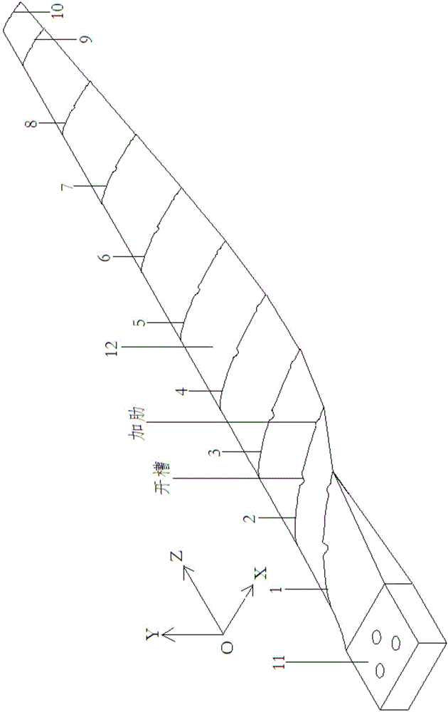
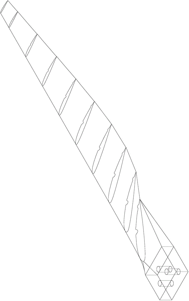
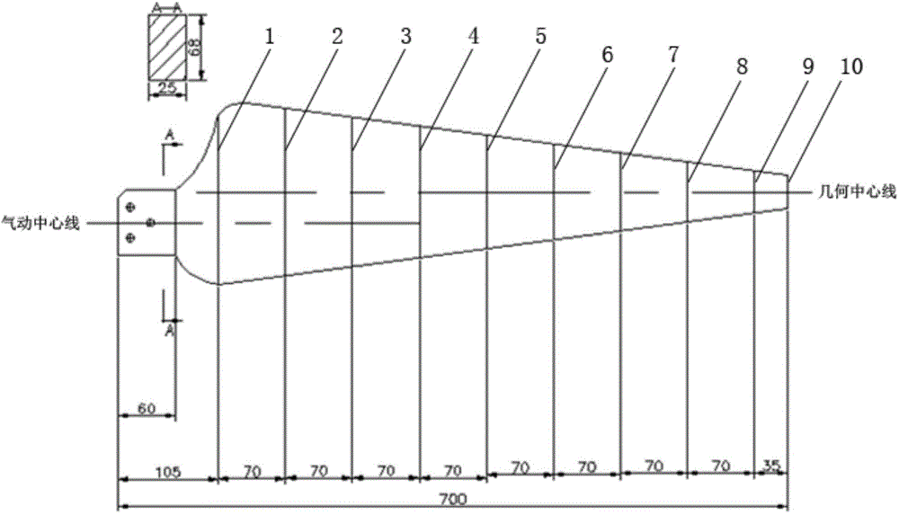
[0036] as attached figure 1 , 2 As shown in and 3, the ribbed and slotted wind turbine blade of the present invention is composed of two parts, the blade airfoil 12 and the blade root 11, the total length of the blade is 700 mm, and the blade airfoil part is formed by continuous smooth transition of ten airfoil surface airfoil curves , as attached Figure 4-13 As shown, the chord lengths corresponding to the ten airfoils are as follows: the first airfoil 1 is 170.0mm, the second airfoil 2 is 153.6mm, the third airfoil 3 is 137.2mm, and the fourth airfoil Surface 4 is 120.7mm, fifth airfoil surface 5 is 104.3mm, sixth airfoil surface 6 is 87.9mm, seventh airfoil surface 7 is 71.4mm, eighth airfoil surface 8 is 55.0mm, ninth airfoil surface The surface 9 is 38.6mm, and the tenth airfoil surface 10 is 30.4mm;

[0037] The airfoil curves of the ten airfoil...


PUM


Abstract

The invention discloses a ribbed and grooved type wind turbine blade and belongs to the technical field of wind power utilization. The surface of the wind turbine blade is formed by ten airfoil-shaped surface airfoil-shaped curves through continuous smooth transition. Each airfoil-shaped surface airfoil-shaped curve is composed of two parts, namely a leeside curve body and a windward side curve body, and each leeside curve body is provided with a downward-concave curve and an upward-convex curve. Ten airfoil-shaped surfaces are sequentially arranged in the blade unfolding direction, and grooved and ribbed structures are formed on the surface of the blade after smooth transition of the downward-concave curves and the upward-convex curves of the leeside curve bodies of the ten airfoil-shaped surfaces. The ribbed and grooved structures on the surface of the blade can effectively resist bending deformation caused by conventional vibration of the blade, and fatigue damage resistant capacity of the blade is improved obviously. Meanwhile, the grooved and ribbed structures on the surface of the blade do not enable pneumatic performance of the blade to be lowered, but the blade has good pneumatic performance.

Description

technical field [0001] The invention relates to a wind turbine blade, in particular to a ribbed and slotted wind turbine blade, which belongs to the technical field of wind energy utilization. Background technique [0002] A wind turbine is a device that absorbs wind energy through the blades of the wind rotor, and then converts mechanical energy into electrical energy. Wind turbine blades are the key power components of wind turbines, which determine the wind energy utilization rate of wind turbines. The wind turbine blade is composed of two parts: the blade airfoil and the blade root. The structure of the blade airfoil determines the aerodynamic performance of the wind wheel. The blade root is mainly responsible for the connection between the blade airfoil and the hub, and plays the role of blade support and positioning. effect. [0003] The structure of the traditional wind turbine blade airfoil is derived from the aviation airfoil, which leads to the following key tech...

Claims


Application Information

Patent Timeline
Patent Type & Authority Patents(China)
IPC IPC(8): F03D1/06
CPCY02E10/72
Inventor 汪建文马剑龙刘雄飞魏海姣董波
Owner INNER MONGOLIA UNIV OF TECH
Why Eureka
Try Eureka