Athermal plasma purifying unit

A non-thermal plasma and purification unit technology, applied in deodorization, disinfection, etc., can solve the problems of high cost, complex structure of air disinfection and purification unit, and increased volume

Active Publication Date: 2013-07-17
ZHEJIANG TIANQING ENVIRONMENTAL PROTECTION TECH CO LTD
View PDF1 Cites 0 Cited by
  • Summary
  • Abstract
  • Description
  • Claims
  • Application Information

AI Technical Summary

Problems solved by technology

This makes the air disinfection and purification unit complex in structure, increased in volume, high in cost, and inconvenient to use.

Method used


Image

  • Athermal plasma purifying unit
  • Athermal plasma purifying unit
  • Athermal plasma purifying unit

Examples


Embodiment 1

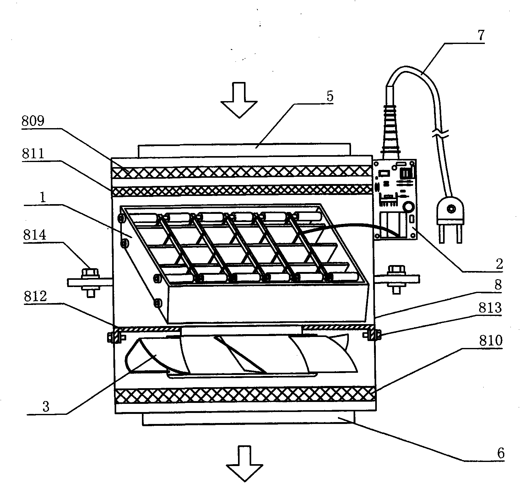
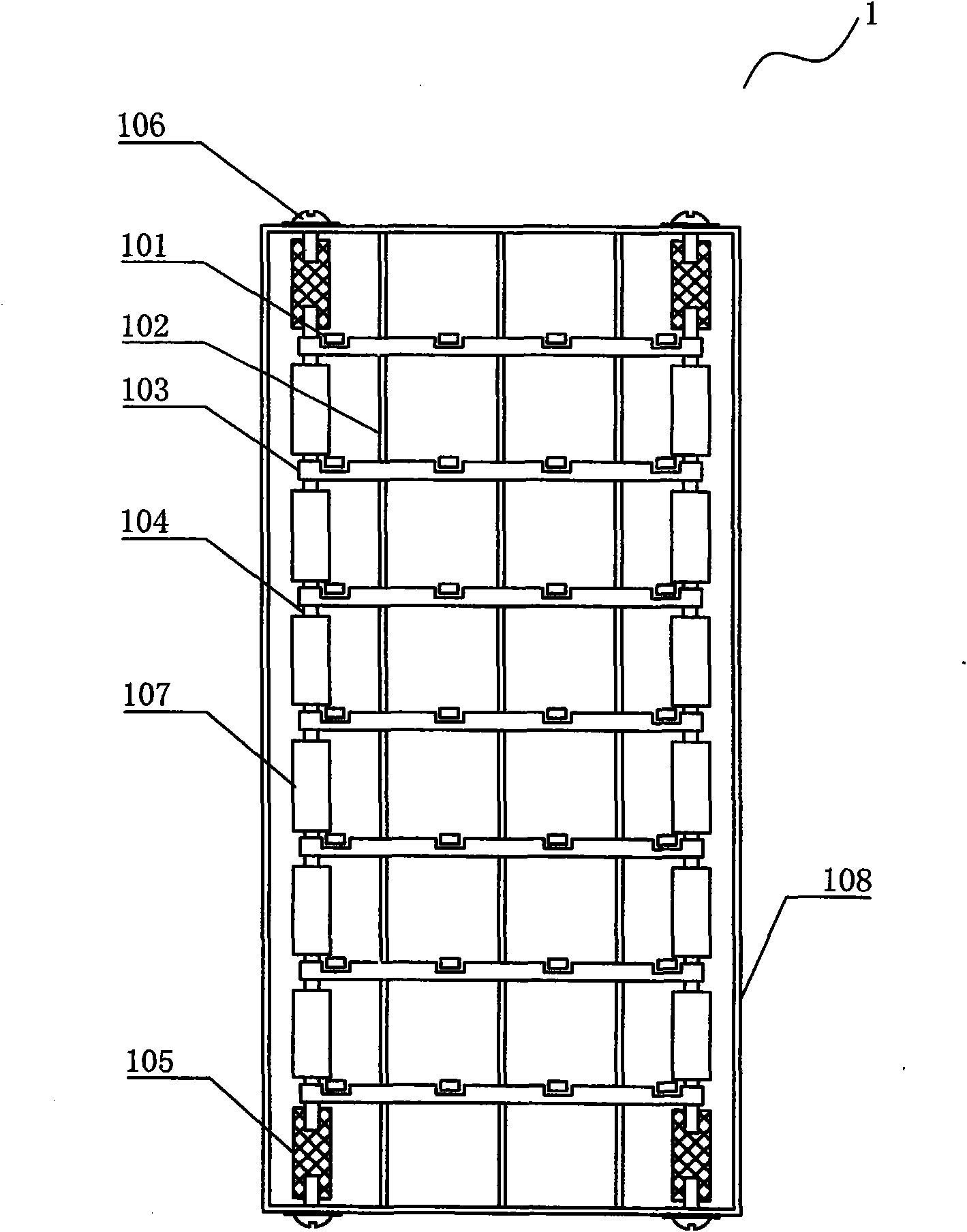
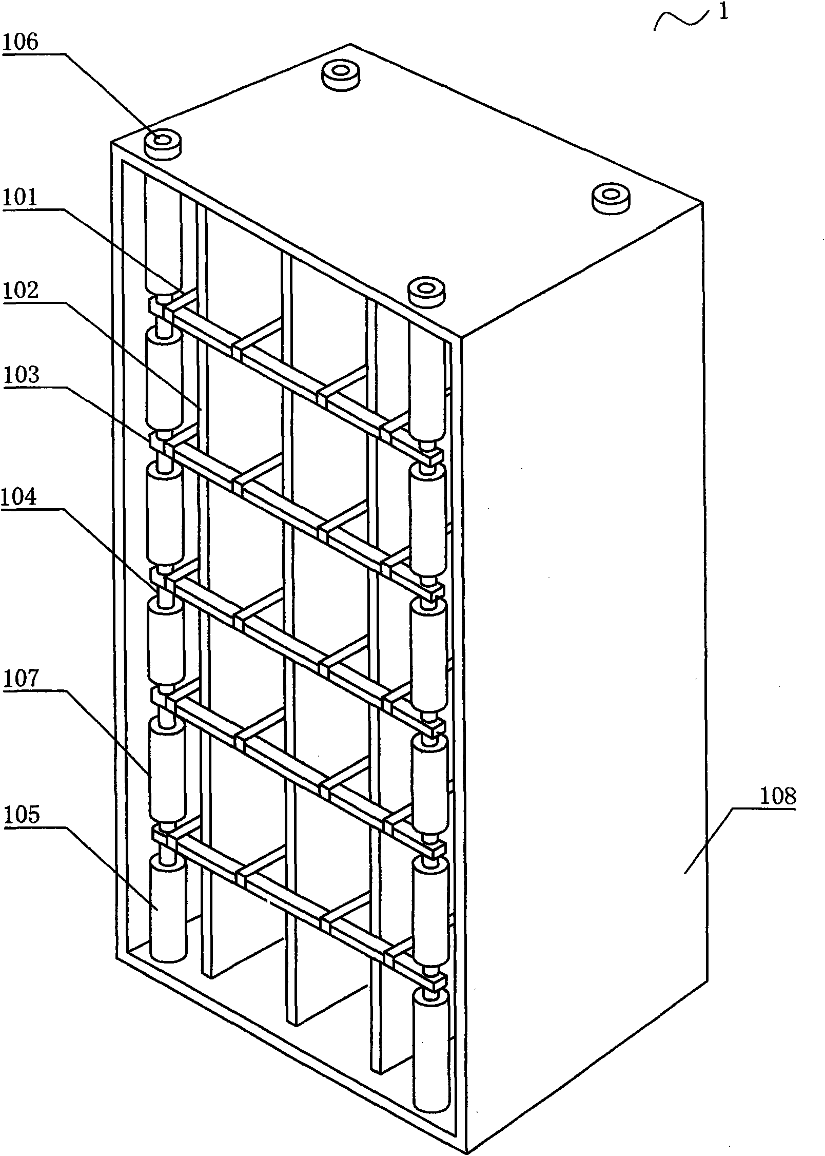
[0071] figure 1 is a schematic structural view of the non-thermal plasma purification unit of the present invention; figure 2 is a front sectional view of the plasma reactor of the present invention; image 3 It is the three-dimensional structure diagram of the plasma reactor of the present invention. The non-thermal plasma purification unit of the present invention comprises a plasma reactor 1, a pulse power supply 2, a fan assembly 3, an air inlet 5, an air outlet 6, a power supply connector 7 and a casing 8, the air inlet 5 is provided with an air filter 809, and the outlet The tuyere 6 is provided with an air filter 810, and the plasma reactor 1 is arranged in the air flow. The plasma reactor 1 is provided with positive electrodes 101 made of several nickel-chromium metal wires or nickel-chromium metal strips arranged in parallel at equal distances in the same plane, and the positive electrodes 101 are placed in the middle of two adjacent negative electrodes 102 . The ...

Embodiment 2

[0083] The anti-microdischarge conductive rail 103 provided by the non-thermal plasma purification unit of the present invention is made of aluminum rods or stainless steel bars, and the two ends of the positive electrodes 101 made of several nickel-chromium wires or nickel-chromium metal strips are fixed on the barriers. The corresponding position on the micro-discharge conductive rail 103 is positioned in the groove; the convex tip can also be used to replace the groove, which is acceptable for fixing the nickel-chromium metal wire, but the problem of skewing will occur when the nickel-chromium metal band is fixed. The inventor designed to use springs and stainless steel sheets to replace the corresponding grooves on the micro-discharge conductive rail 103 to fix the nickel-chromium metal wires and nickel-chromium metal strips. The elastic instability of the stainless steel sheet causes the nickel-chromium wire and the metal strip to sway even more. In severe cases, the posit...

Embodiment 3

[0085] The pulse transformer 206 provided by the non-thermal plasma purification unit of the present invention is provided with a multi-slot insulating bobbin 212, and the secondary coil 215 is divided into three sections, four sections or five sections and wound on the multi-slot insulating bobbin 212. connected in series in the groove. Generally speaking, the distributed capacitance of the windings wound in three sections is about one-ninth of the original, and the distributed capacitance of the windings wound in five sections is about one twenty-fifth of the original. The output end of the pulse transformer 206 is provided with a high voltage wire 213 connected to the anode of the plasma reactor 1 . The withstand voltage parameter of high-voltage fast recovery diode 217 is at least 12KV, and the recovery time is less than 80nS; Core 216 is electromagnetically coupled. The magnetic core 216 is an iron-based ultramicrocrystalline iron core, and the magnetic circuit is provi...


PUM

PropertyMeasurementUnit
diameteraaaaaaaaaa
widthaaaaaaaaaa
thicknessaaaaaaaaaa

Abstract

The invention relates to an athermal plasma purifying unit, belonging to the technical field of air sterilization and purification. The athermal plasma purifying unit comprises a plasma reactor, a pulse power source, a fan assembly, an air inlet, an air outlet, a power source coupler and an outer case. A positive electrode comprising a plurality of nickel-chromium metal wires or metal straps is arranged in the reactor, and both ends of the positive electrode are fixed in corresponding grooves or protrusions on a conductor rail for preventing micro discharge. The pulse power source is providedwith a digital control circuit, an oscillator, an error amplifier and a PWM (Pulse-Width Modulation) comparator are arranged in the digital control circuit, and the operating current of the plasma reactor is converted into a digital control current to control the width of an output pulse. The invention effectively stops the micro discharge phenomenon of the reactor and prolongs service life, and the high-voltage pulse current can increase the concentration of the plasma, can improve air sterilization and purification efficiency and can save energy. The athermal plasma purifying unit can be widely applied to places having high requirements for cleanness, such as factory clean rooms, hospital operating rooms, isolation wards and the like, and can also be applied to the air sterilization andpurification of places such as office buildings, theatres, trains, automobiles, subways and the like.

Description

Technical field: [0001] The invention belongs to the technical field of air disinfection and purification, and in particular relates to a non-thermal plasma purification unit. Background technique: [0002] The air disinfection and purification units commonly used in clean rooms such as semiconductor factories, pharmaceutical factories, food factories and hospital operating rooms mainly include filter adsorption type, electronic electrostatic adsorption type, ozone disinfection type, ultraviolet disinfection type, photocatalytic purification, etc. kind. [0003] The filter adsorption type is currently the air disinfection and purification unit selected by most clean rooms, and the common ones are high-efficiency air filters and FFUs. It uses the van der Waals force between the surfaces of objects to absorb suspended particle pollutants in the air and purify the air. It can only filter out dust, but cannot be thoroughly sterilized; the filtration resistance increases with t...

Claims


Application Information

Patent Timeline
Patent Type & Authority Patents(China)
IPC IPC(8): A61L9/22
Inventor 周云正
Owner ZHEJIANG TIANQING ENVIRONMENTAL PROTECTION TECH CO LTD
Why Eureka
Try Eureka