
Wire rod coiling method

A wire winding method and wire technology, applied in the field of wire winding, can solve problems such as crossing another magnetic pole 1b, limiting the movement range of the wire nozzle 6, and returning to the coil portion 5 side.

Active Publication Date: 2012-10-31
NITTOKU ENG CO LTD
View PDF0 Cites 0 Cited by
  • Summary
  • Abstract
  • Description
  • Claims
  • Application Information

AI Technical Summary

Problems solved by technology

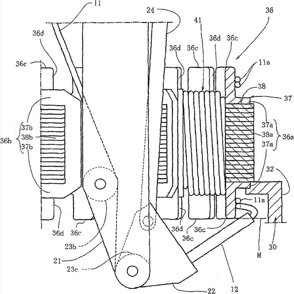
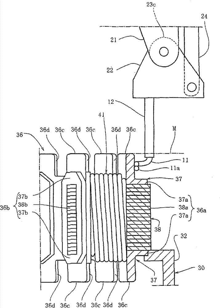
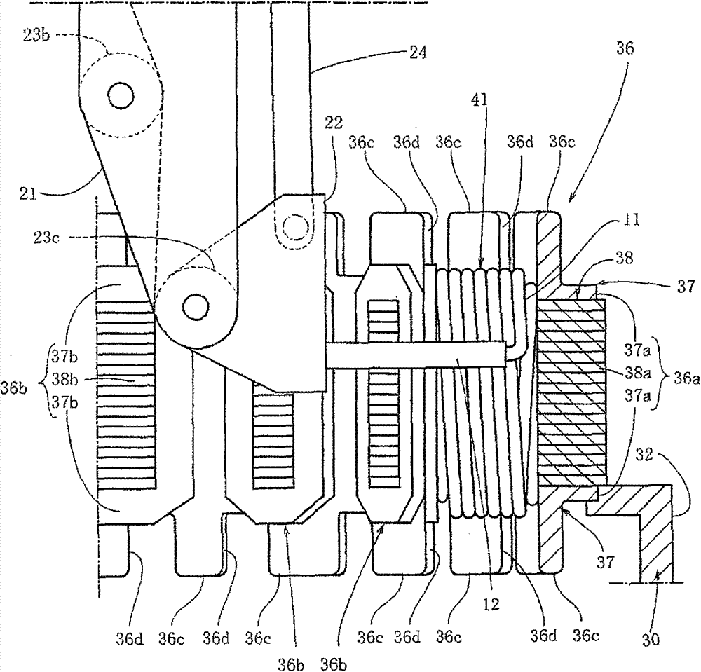
[0008] However, the front end of the lead-out wire 4 of the nozzle 6 in the horizontal state is located outside the protruding end of the extension portion 1c in the axial direction of the annular portion 1a, and the wire is wound outside the extension portion 1c in this state. 4, there is the following problem: the wire 4 returns to the side of the coil part 5 from the gap between the nozzle 6 and the extension part 1c as shown by the dotted line, so that the connecting wire part 4a crosses the other magnetic pole 1b Case
[0009] In order to solve this problem, during the winding, it is necessary to move the front end of the nozzle 6 farther radially outward than the extension part 1c, and to hang the wire 4 drawn out from the front end on the extension part 1c reliably. However, the nozzle 6 will be elongated, and the range of movement of the nozzle 6 will be limited due to the elongation, which in turn will limit the types of workpieces 1 that can be wound.

Method used


Image

  • Wire rod coiling method
  • Wire rod coiling method
  • Wire rod coiling method

Examples


Embodiment Construction

[0024] Next, the best mode for carrying out the present invention will be described with reference to the drawings.

[0025] Figure 5 The winding machine 10 used for the method of this invention is shown. This winding machine 10 is provided with the base 14 provided in the installation place, and the drive unit 13 provided on the base 14 for driving the nozzle 12 which draws out the wire 11. As shown in FIG. The drive unit 13 is composed of drive units 16 , 17 , and 18 in three axial directions, and includes a front-rear direction drive unit 16 , a left-right direction drive unit 17 , and a vertical direction drive unit 18 . The driving units 16 , 17 , and 18 are substantially identical driving mechanisms along the driving directions X, Y, and Z.

[0026] First, the up-down direction drive unit 18 will be described. The up-down direction drive unit 18 is provided with: an up-and-down guide rail 18a arranged along the driving direction Z; Bolts are provided; a vertical movi...


PUM


Abstract

The invention provides a wire rod coiling method, which is capable of not limiting the variety of coiling workpieces, and preventing the wire rod exported from the wire mouth from returning to a coil part side through the gap between the wire mouth and an extension part. The wire coiling method comprises the steps of winding the wire rod exported from the front of the wire mouth on a magnetic pole extruded from an annular part along a radial direction; coiling the wire rod on the extension part disposed at the annular part along an axial direction; coiling the wire rod exported from the frontof the wire mouth on another magnetic pole. The invention is characterized in that the front end of the wire mouth in wire coiling intersects with an imaginary surface or is disposed at a position which is nearer to the annular part side than the imaginary surface; the imaginary surface is vertical to the axis of the annular part and contact with the extruding end of the extension part. Preferably speaking, the wire mouth can be installed with a changeable direction on a ruler-shaped wire mouth supporting part which is movably inserted in the annular part, and at the time of coiling, the wiremouth is parallel to the supporting part or inclined with respect to the supporting part.

Description

technical field [0001] The present invention relates to a wire winding method. After winding the wire led out from the front end of the wire nozzle on one of the plurality of magnetic poles protruding in the radial direction of the annular part, the wire is wound on the magnetic pole formed in the ring. On the extended part of the shaped part, and then wind the wire on another magnetic pole. Background technique [0002] Conventionally, a stator of a rotating electrical machine or a stator incorporated in a resolver such as a brushless motor has a workpiece having an annular portion and a plurality of magnetic poles extending radially inward from the inner peripheral side of the annular portion. The coil part is formed by winding a wire such as a lead wire around the magnetic pole. [0003] Such as Figure 7 and Figure 8 As shown, as a wire winding machine for forming the coil portion 5, a winding machine having the following configuration has been proposed. Part 7, whic...

Claims


Application Information

Patent Timeline
Patent Type & Authority Patents(China)
IPC IPC(8): H02K15/08
CPCH02K15/095
Inventor 加藤亮
Owner NITTOKU ENG CO LTD
Learn More