Check patentability & draft patents in minutes with Patsnap Eureka AI!

Device and method for detecting motion vector, device and method for encoding moving image, and device and method for decoding moving image

A motion vector and motion image technology, applied in image communication, television, electrical components, etc., can solve the problems of reduction and limitation of code size, and achieve the effect of reducing code size

Active Publication Date: 2010-12-22
OKI ELECTRIC IND CO LTD
View PDF0 Cites 1 Cited by
  • Summary
  • Abstract
  • Description
  • Claims
  • Application Information

AI Technical Summary

Problems solved by technology

[0005] However, in H.264 / AVC standard variable block size motion compensation, when the partition and motion vector of the optimal size are obtained, the motion vector information of the partition is encoded, even if there is a nearby motion that can be regarded as the same The partitions involved in the vector must also encode the motion vector information for each partition, so there is a limitation in the reduction of the code amount

Method used


Image

  • Device and method for detecting motion vector, device and method for encoding moving image, and device and method for decoding moving image
  • Device and method for detecting motion vector, device and method for encoding moving image, and device and method for decoding moving image
  • Device and method for detecting motion vector, device and method for encoding moving image, and device and method for decoding moving image

Examples


no. 1 Embodiment approach

[0031] Hereinafter, a first embodiment of a motion vector detection device and method, a video encoding device and method, and a video decoding device and method according to the present invention will be described with reference to the drawings.

[0032] (A-1) Video coding device of the first embodiment

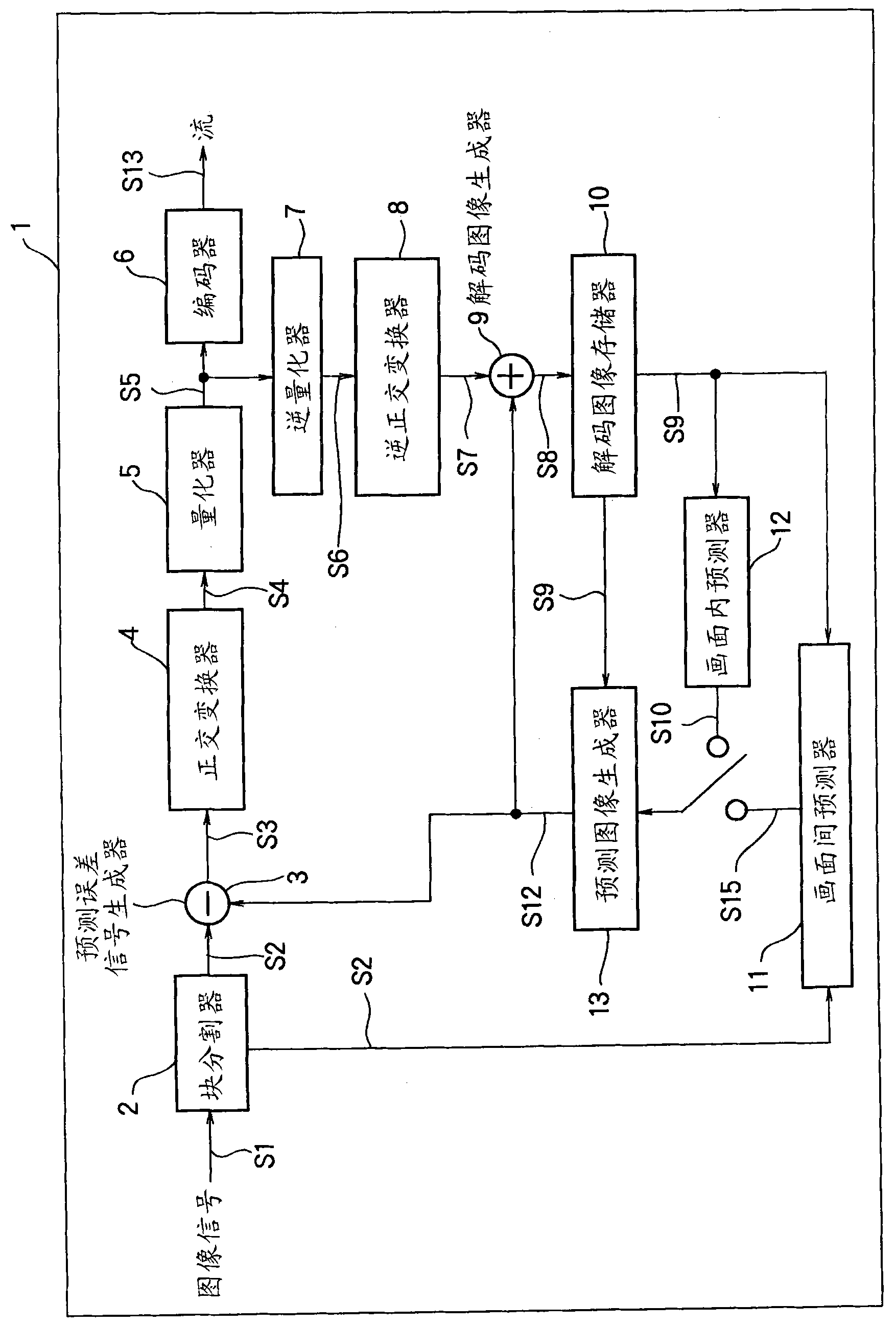
[0033] figure 2 It is a block diagram showing the overall configuration of the video encoding device 1 according to the first embodiment. The video coding device 1 of the first embodiment is generally a device conforming to the H.264 / AVC standard, for example.

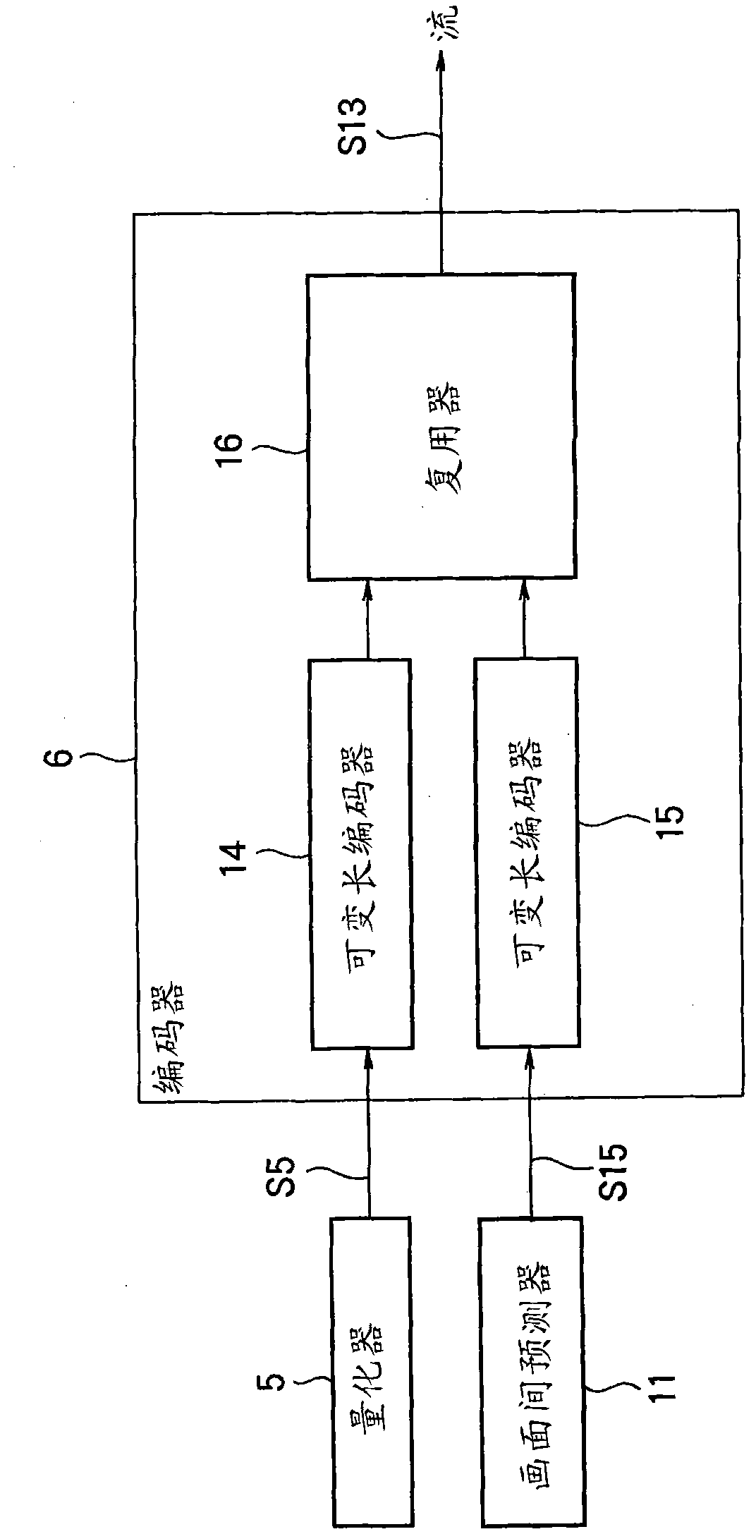
[0034] exist figure 2 Among them, the moving image encoding device 1 has: a block divider 2, a prediction error signal generator 3, an orthogonal transformer 4, a quantizer 5, an encoder 6, an inverse quantizer 7, an inverse orthogonal transformer 8, and a decoded image generator 9, a decoded image memory 10, an inter predictor 11, an intra predictor 12, and a predictive image generator 13.

[0035] The block d...

no. 2 Embodiment approach

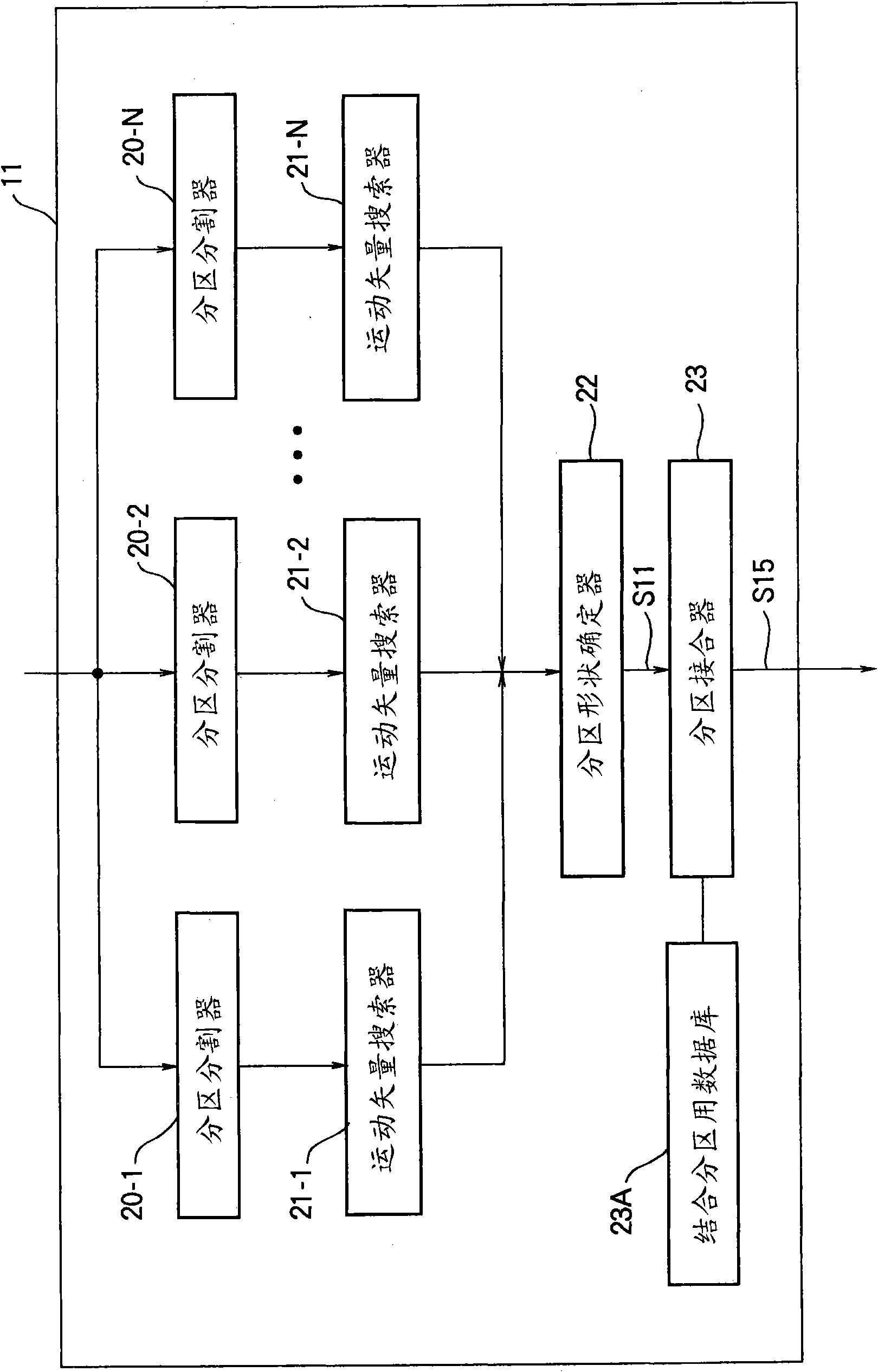
[0133] Next, a second embodiment of the motion vector detection device and method, video encoding device and method, and video decoding device and method of the present invention will be described. In addition, the first embodiment can be figure 1 , figure 2 , Figure 8 , Figure 9 , Figure 10 , Figure 11 As it is, it is a drawing of the second embodiment.

[0134] In the first embodiment described above, when the partition combiner 23 combines the partitions based on the motion vector information output from the partition shape determiner 22, if there are partitions with the same reference image and motion vector, the positions of these partitions Relationships combine partitions independently.

[0135] However, in combining partitions like the first embodiment, there are extremely many types of partitions after combining. Therefore, the code amount of the macroblock type for determining the shape of the combined partition increases, which may cancel out the reducti...


PUM


Abstract

A device for detecting a motion vector which acquires information on the motion vector with a plurality of partitions of different sizes and rectangular shapes as a unit for each block of a predetermined size in which one screen is divided, the sizes of the blocks being the upper limit, comprises a partition combining means (23) for, if motion vectors for one of the blocks can be obtained in the plurality of partitions, determining whether or not to combine the plurality of partitions in which the motion vectors have been obtained and, when combining the plurality of partitions, including information on the motion vectors of the partitions after combination in information on a motion vector outputted from the device. The code amount associated with the motion vector can be suppressed.

Description

technical field [0001] The present invention relates to a motion vector detection device and method, a moving picture encoding device and method, and a moving picture decoding device and method, and can be applied to moving picture encoding and decoding in accordance with the H.264 / AVC standard, for example. Background technique [0002] In most moving image coding methods including the H.264 / AVC standard, one image (one frame) is divided into multiple blocks, and the motion relative to the encoded image is predicted on a block-by-block basis. motion compensation. The smaller the block size of the motion compensation, the finer the prediction can be performed, but since it is necessary to encode the motion vector information for each block, the code amount increases. [0003] Therefore, in the H.264 / AVC standard, a strategy of switching from several motion compensation block sizes (hereinafter referred to as partitions) to select the optimal block size (motion compensation ...

Claims


Application Information

Patent Timeline
IPC IPC(8): H04N7/32H04N19/50H04N19/119H04N19/134H04N19/136H04N19/139H04N19/157H04N19/189H04N19/196H04N19/423H04N19/46H04N19/503H04N19/51H04N19/513H04N19/593H04N19/60H04N19/61H04N19/70
CPCH04N19/00781H04N19/00884H04N19/00133H04N19/0026H04N19/00587H04N19/00678H04N19/00072H04N19/00151H04N19/00545H04N19/119H04N19/134H04N19/139H04N19/17H04N19/46H04N19/51H04N19/57H04N19/61H04N19/70
Inventor 莲尾知志
Owner OKI ELECTRIC IND CO LTD
Features
  • R&D
  • Intellectual Property
  • Life Sciences
  • Materials
  • Tech Scout
  • Unparalleled Data Quality
  • Higher Quality Content
  • 60% Fewer Hallucinations
Learn More