Rotor wing disk-shaped aviation aircraft

A technology for rotor discs and aircraft, which is applied in aircraft, motor vehicles, transportation and packaging, etc., can solve problems such as high energy consumption, heavy take-off and landing conditions, and limited air movements.

Inactive Publication Date: 2010-12-29
李文奇
View PDF6 Cites 6 Cited by
  • Summary
  • Abstract
  • Description
  • Claims
  • Application Information

AI Technical Summary

Problems solved by technology

[0002] Currently known aviation vehicles adopt the principle of super-high-power power to directly push (pull) the flying body to displace the flying body and accelerate the displacement until reaching a certain speed. limit, take-off and landing conditions

Method used


Image

  • Rotor wing disk-shaped aviation aircraft
  • Rotor wing disk-shaped aviation aircraft

Examples


Embodiment Construction

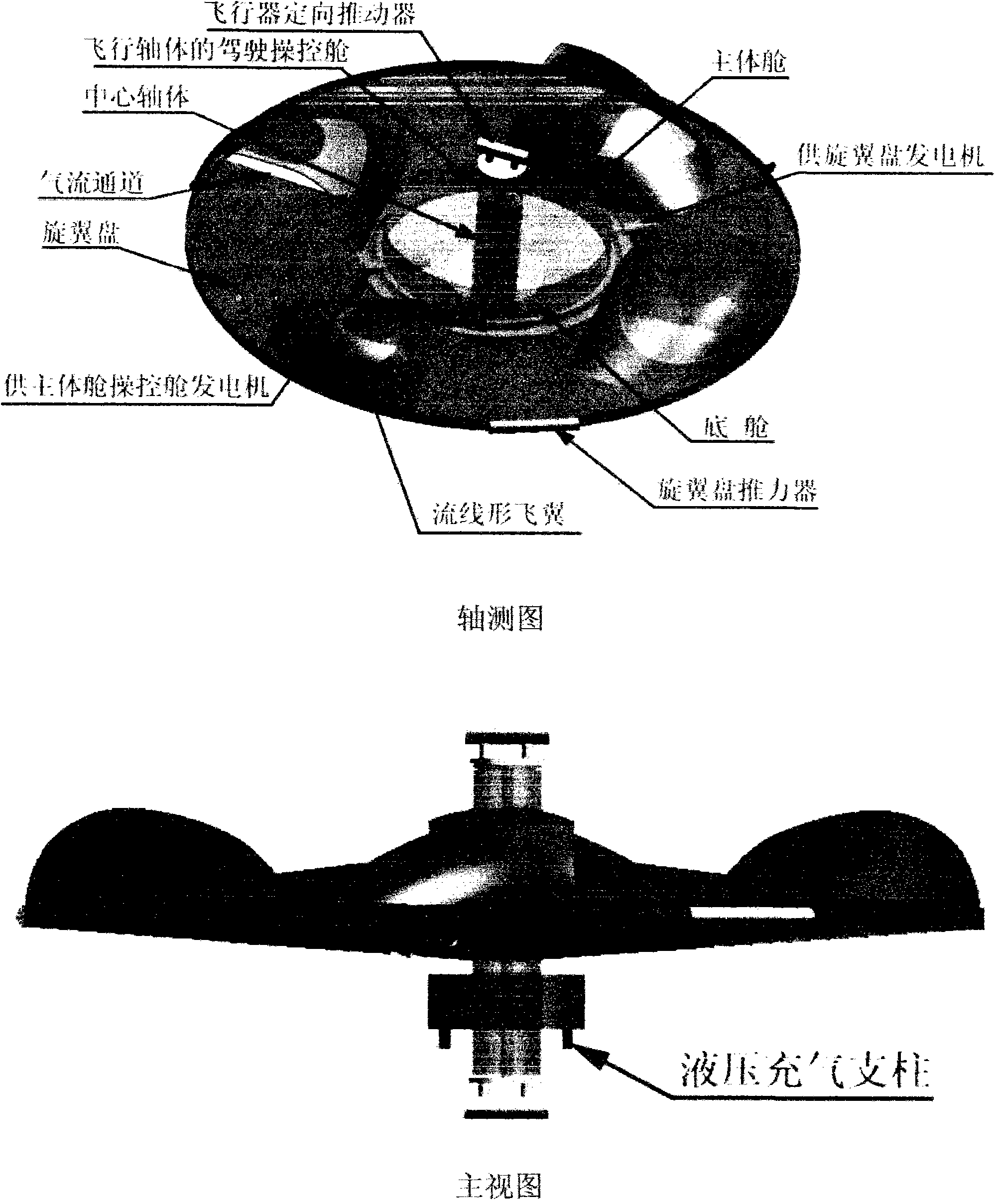
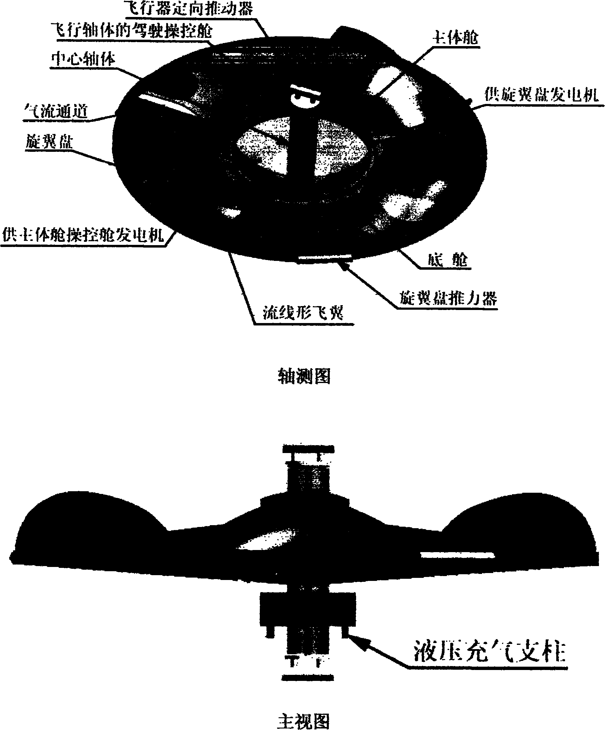
[0005] The design structure of the aircraft is relatively simple, and the current existing technology can implement and make it fly. Its specific implementation is as follows: A hollow cylinder is fixed up and down by two bearings with the same diameter, and is divided into upper, middle and lower parts (shown in the figure). The upper, lower and central parts of the rotor disc are respectively connected with the upper and lower bearings on the central shaft as a whole (as shown in the figure). The expansion space in the middle section of the hollow shaft is the main cabin (pictured). The upper part of the hollow shaft body is designed as a driving control cabin. Powerful rotor disc; streamlined flying wing and airflow channel under the streamlined flying wing are designed (pictured), and three thrusters are designed and installed on the edge of the rotor disc to push the flexible rotor disc to rotate at high speed (pictured). When the rotor disk rotates at a high speed, a s...


PUM


Abstract

The invention discloses a rotor wing disk-shaped aviation aircraft, which is a novel aviation aircraft with a flight principle different from that of the conventional worldwide known aircrafts. The appearance is designed to an oblate spheroid shape and is similar to a top of a gyroscope. The rotor wing disk-shaped aviation aircraft consists of five major parts: a rotor wing disk, a hollow shaft body, namely a driving control cabin, a main cabin body, a rotor wing disk impeller, a directional thruster and a landing hydraulic inflated pillar, has the main characteristic of low energy consumption, and has the advantage of capacity of realizing vertical amphibious launching and landing, origin suspension, zero-gyration supersonic flight, cheap launching and landing sites, steady landing and the like.

Description

technical field [0001] Rotor disc-shaped aviation vehicle is a new type of aviation vehicle that is different from the current world aviation vehicle principle. Background technique [0002] Currently known aviation vehicles adopt the principle of super-high-power power to directly push (pull) the flying body to displace the flying body and accelerate the displacement until reaching a certain speed. The limit, the take-off and landing conditions are engraved. The rotor disc-shaped aviation aircraft is designed to use low-power power to drive the flexibly rotating rotor disc to rotate at a high speed. This creates a strong airflow. The airflow acts on: 1. the rotor disc, 2. the streamlined flying wing on the rotor disc, and 3. the airflow channel under the streamlined flying wing. Powerful airflow and air pressure lift the flying body into the air. After the flying body is vacated, use the two directional flight propellers designed on the top and bottom of the control cab...

Claims


Application Information

Patent Timeline
Patent Type & Authority Applications(China)
IPC IPC(8): B64C39/06
Inventor 李文奇
Owner 李文奇
Why Eureka
Try Eureka