Electrical junction box

A technology of electrical junction boxes and fuses, which is applied in the direction of circuits, electrical components, circuits or fluid pipelines, and can solve problems such as fuse drop and damage

Inactive Publication Date: 2010-12-29
SUMITOMO WIRING SYST LTD
View PDF5 Cites 7 Cited by
  • Summary
  • Abstract
  • Description
  • Claims
  • Application Information

AI Technical Summary

Problems solved by technology

Therefore, there is a problem that the cover member colli

Method used


Image

  • Electrical junction box
  • Electrical junction box
  • Electrical junction box

Examples


Embodiment Construction

[0031] Referring now to the drawings, an embodiment of an electrical junction box according to the present invention will be described below. In general, the referenced top and bottom surfaces are described with respect to the electrical junction box in the installed position in which the housing body 12 is located below the cover member 14 .

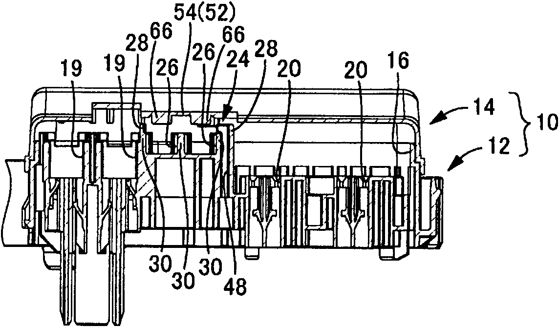
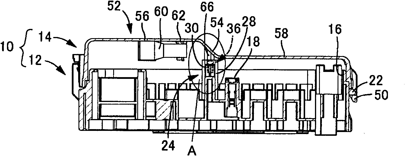
[0032] figure 1 with 2 A relay box 10 is shown as one embodiment of the electrical junction box according to the present invention. The relay box 10 includes a case body 12 and a cover member 14 for covering the case body 12 . The electrical junction box is not limited to the disclosed relay box. The electrical junction box may be a junction block, a fuse box, or the like.

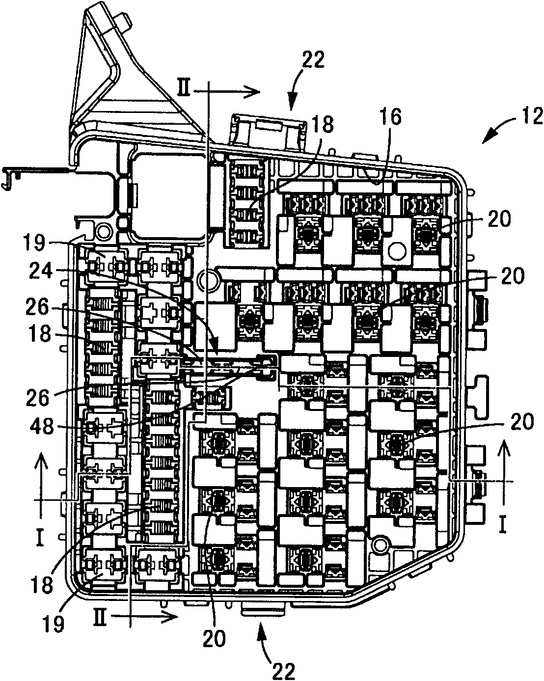
[0033] image 3Housing body 12 is shown. The housing body 12 may be formed in a substantially rectangular parallelepiped configuration made of a synthetic resin material and having an opening 16 opened substantially upward in the mounting direction. The housi...


PUM


Abstract

The invention provides an electrical junction box having a new structure that can prevent an unused fuse from being broken and can easily house and remove the unused fuse. A casing body (12) is provided with an unused fuse containing section (24) that is open in the same direction as an opening direction of the casing body (12). The unused fuse containing section (24) is provided on a periphery with at least one protective wall (28). A cover member (14) for closing an opening (16) in the casing body (12) is provided at a position opposed to the unused fuse containing section (24) with a presser portion (66) for preventing an unused fuse (36) from disconnecting from the unused fuse containing section (24).

Description

[0001] References [0002] This application claims priority from JP 2009-150237 filed in Japan on Jun. 24, 2009, the entire contents of which are hereby incorporated by reference. technical field [0003] The present invention relates to an electrical junction box mounted on a motor vehicle or the like, and more particularly to an electrical junction box including a structure capable of holding an unused fuse. Background technique [0004] Heretofore, electric circuits in motor vehicles and the like are provided with fuses for preventing overcurrent. Fuses are assembled and arranged in electrical junction boxes such as fuse boxes. When any one of the fuses is melted by an overcurrent, the melted fuse must be replaced with a new one in the electrical junction box. When a dark current circuit, such as a clock, that consumes electrical power at all times is disconnected, the dark current fuse must be removed from the fuse mount. [0005] Now, a special electric junction box ...

Claims


Application Information

Patent Timeline
IPC IPC(8): H02G3/16B60R16/02
CPCH01H85/26H01H2085/208H01H85/2045B60R16/0239
Inventor 水上俊介
Owner SUMITOMO WIRING SYST LTD
Why Eureka
Try Eureka