

Portable electronic device
An electronic device and portable technology, applied in the direction of batteries, circuits, electrical components, etc., can solve the problems of increasing the volume and cost of electronic devices, poor hand feel, etc., and achieve the effects of easy battery removal, good hand feel, and space saving
- Summary
- Abstract
- Description
- Claims
- Application Information
AI Technical Summary
Problems solved by technology
Method used
Image

Examples
Embodiment Construction
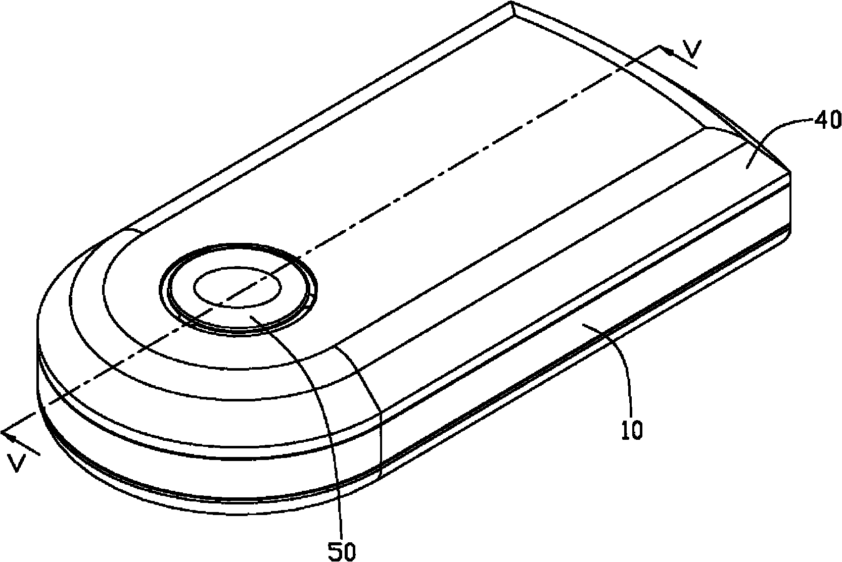
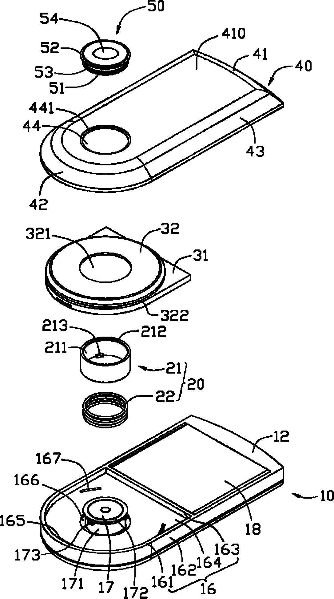
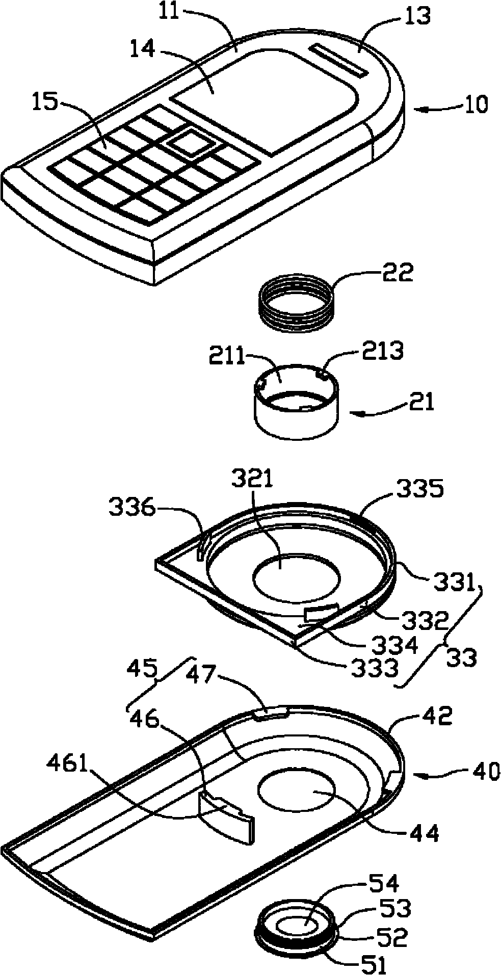
[0014] see figure 1 and figure 2 A portable electronic device according to a preferred embodiment of the present invention includes a body 10 , an antenna cover 30 disposed on the body 10 , a battery cover 40 and a lens cover 50 fixed on the battery cover 40 .
[0015] The body 10 can be a main body of a portable electronic device. The main body 10 is roughly a cuboid, which includes a panel 11, a back surface 12 opposite to the panel 11, an end 13, a display screen 14 and a keyboard area 15 arranged on the panel 11, a first mounting portion 16, A camera assembly 17 , an accommodating slot 18 and an engaging member 20 . The end portion 13 is semicircular, and the display screen 14 is disposed close to the end portion 13 .
[0016] The first mounting portion 16 is a groove recessed on the back surface 12 adjacent to the end portion 13 . The first mounting portion 16 includes a semicircular groove wall 161 , two parallel opposite groove side walls 162 , a groove end wall 16...
PUM
 Abstract
Description
Claims
Application Information