Supercharge Your Innovation With Domain-Expert AI Agents!

Steam system

一种蒸汽系统、蒸汽的技术,应用在蒸汽系统领域,达到结构以及控制简易、效率好、防止浪费的效果

Active Publication Date: 2010-12-29
MIURA COMPANY LIMITED
View PDF7 Cites 2 Cited by
  • Summary
  • Abstract
  • Description
  • Claims
  • Application Information

AI Technical Summary

Problems solved by technology

That is, none of the inventions disclosed in the patent documents is a technology for controlling the supply of steam to the steam engine based on both the usage load of the steam at the location where the steam from the steam engine is supplied and the usage load of the fluid discharged from the compressor.

Method used


Image

  • Steam system
  • Steam system
  • Steam system

Examples


Embodiment 1

[0076] Hereinafter, specific examples of the present invention will be described in detail based on the drawings.

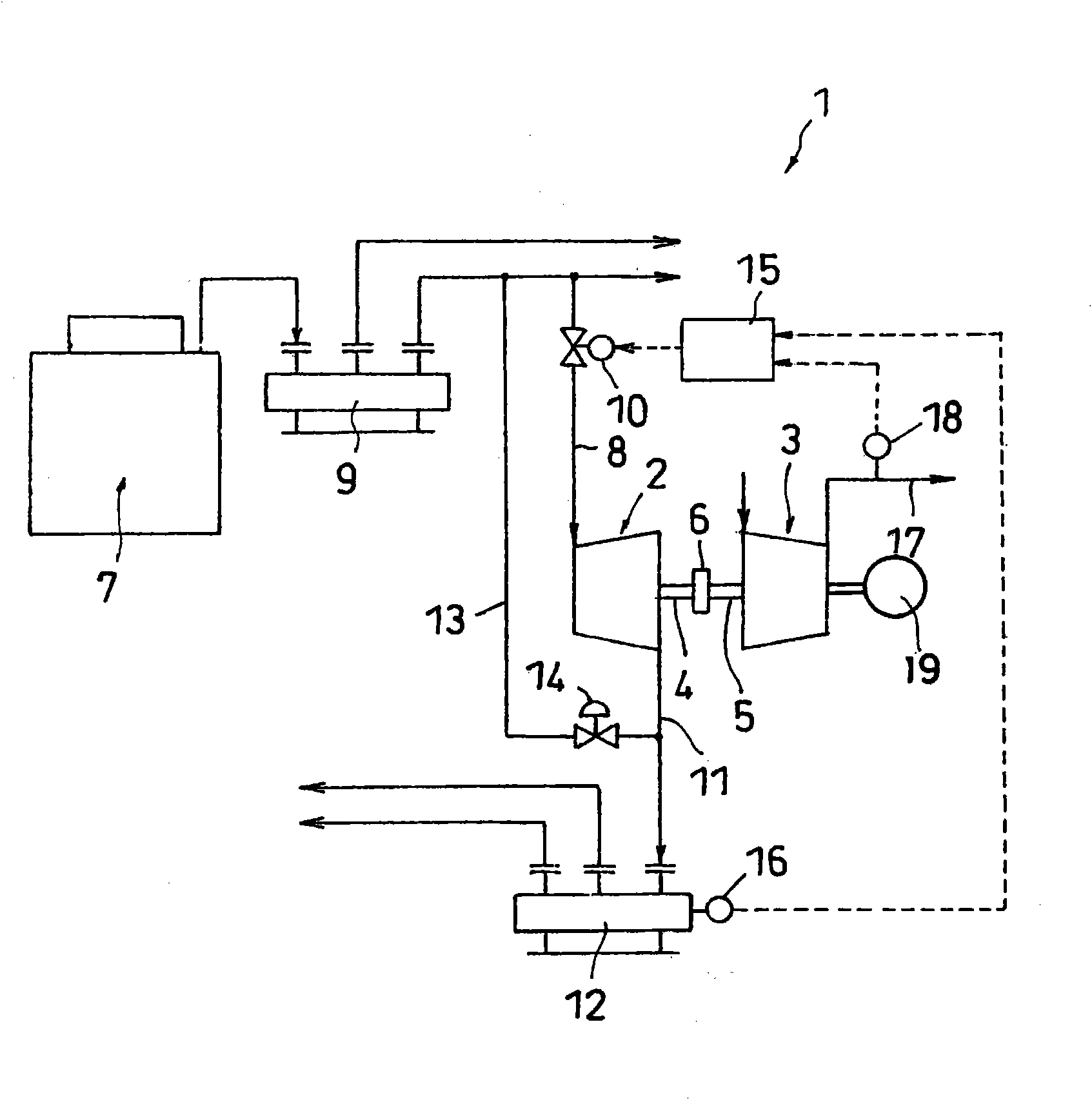
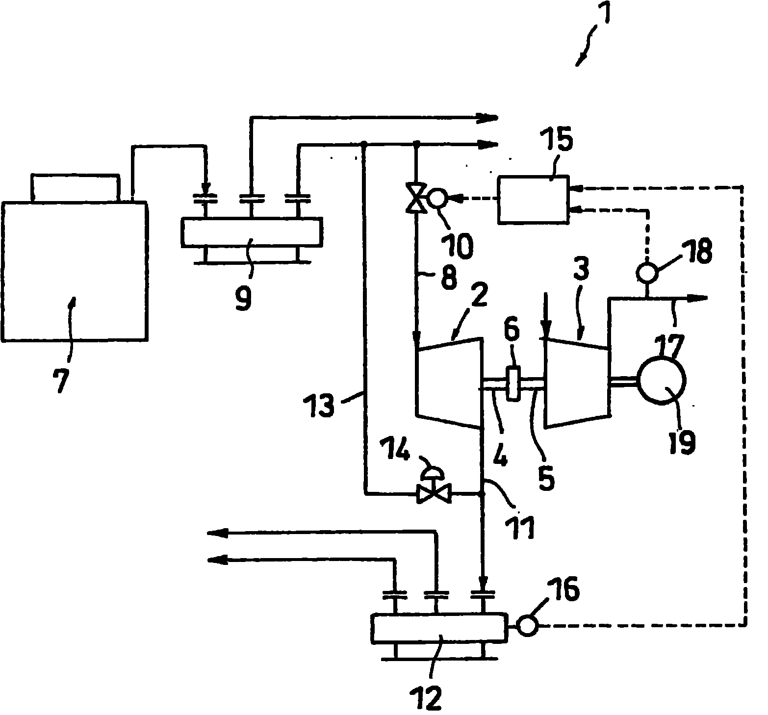
[0077] figure 1 It is a schematic diagram showing Example 1 of the steam system of the present invention. The steam system 1 of this embodiment has a prime mover 2 that generates power using steam, and a driven machine 3 driven by the prime mover 2 .

[0078] The prime mover 2 is a steam system that receives steam to generate power. The steam engine 2 may be a steam turbine, but is suitably a screw steam engine. A screw steam engine is a device that introduces steam between meshing screw rotors, uses the steam to rotate the screw rotors, expands and depressurizes the steam, and obtains power from the rotation of the screw rotors at this time.

[0079] The driven machine 3 is driven by the steam engine 2 and ejects or sucks fluid. Specifically, the driven machine 3 is a pump, a blower, a compressor, or a vacuum pump. The driven machine 3 of this embodiment is...

Embodiment 2

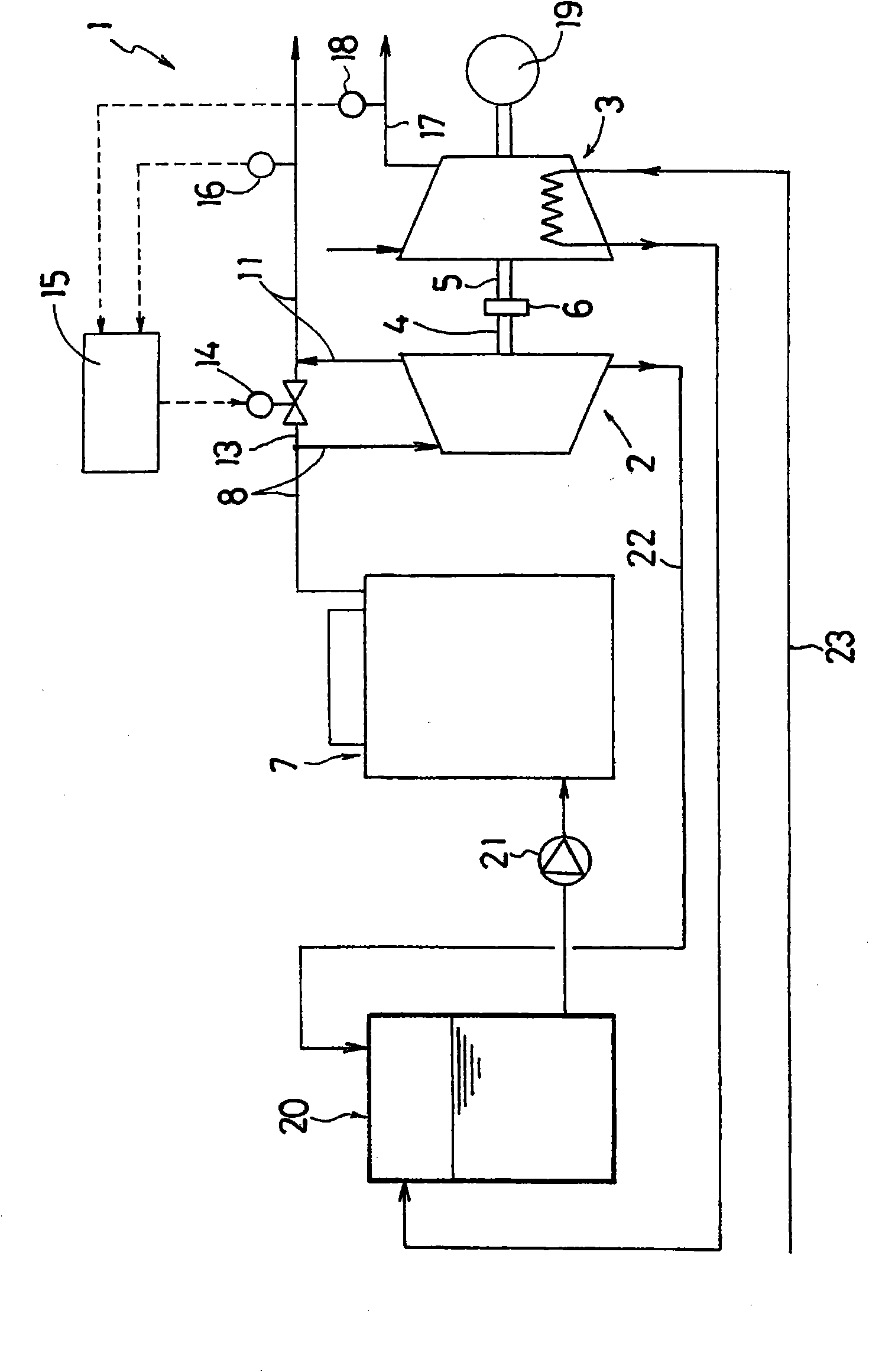
[0096] figure 2 It is a schematic diagram showing Example 2 of the steam system 1 of the present invention. The steam system 1 of the second embodiment is basically the same as that of the first embodiment. Therefore, in the following description, the differences between the two will be mainly described, and the corresponding parts will be described with the same reference numerals.

[0097] The steam system 1 of the second embodiment also has a steam system 2 that generates power using steam, and a compressor 3 driven by the steam system 2 .

[0098] The steam engine 2 of this embodiment is also a screw type steam engine. Steam from the furnace 7 is supplied to the steam engine 2 through the steam supply path 8 , and the steam used by the steam engine 2 is sent to a steam utilization device (not shown) through the steam discharge path 11 . At this time, as in the first embodiment, the steam from the boiler 7 may also be supplied to the first steam header tank 9 ( figure 1 ...


PUM


Abstract

When driving an air compressor using a steam engine, not only the usage load of compressed air but also that of steam is considered for control. The air compressor (3) is driven by the steam engine (2) which generates motive power using the steam. The steam engine (2) is supplied with the steam through a steam supply path (8) and discharges the steam through a steam discharge path (11). The steam from the steam engine (2) is supplied to a steam using device through a steam header (12). The usage load of the steam is monitored by a pressure sensor (16) provided at the steam header (12). The compressed air from the air compressor (3) is supplied to a compressed air using device through a compressed air path (17). The usage load of the compressed air is monitored by a pressure sensor (18) provided at the compressed air path (17). On the basis of the usage load of the steam and that of the compressed air, supply of the steam to the steam engine (2) is controlled.

Description

technical field [0001] The present invention relates to a steam system that uses steam to drive a compressor and the like to reduce power consumption. [0002] The present application claims priority based on the patent application No. 2008-055686 filed in Japan on March 6, 2008 and the patent application No. 2008-212381 filed in Japan on August 21, 2008, the contents of which are quoted here. Background technique [0003] A method is disclosed in the following patent document 1, which uses a screw-type expander (1) to drive an air compressor (2), and uses a regulating valve (10) to control and deal with the flow into the screw when the load of the air compressor (2) changes. type expander (1) and controls the bypass valve (9) provided between the steam inflow side and the steam outflow side of the screw type expander (1), thus, not being affected by said load change will The back pressure of the steam on the steam outflow side is kept constant. Here, the control of the by...

Claims


Application Information

Patent Timeline
Patent Type & Authority Applications(China)
IPC IPC(8): F01D15/08F01B23/08F01C13/04F01D17/24F01K7/38
CPCF01D15/08F02C3/04F02C6/06F05D2220/72F01K7/38
Inventor 吉成佑治越智康夫古川英夫田中靖国冈本裕介马场一高
Owner MIURA COMPANY LIMITED
Features
  • R&D
  • Intellectual Property
  • Life Sciences
  • Materials
  • Tech Scout
  • Unparalleled Data Quality
  • Higher Quality Content
  • 60% Fewer Hallucinations
Learn More