Optical proximity sensor package

A technology of optical proximity, ambient light sensor, applied in the field of proximity sensor, can solve the problems of different quality, difficult to manufacture, increase of sensor 10, etc.

Active Publication Date: 2011-01-05
AVAGO TECH INT SALES PTE LTD
View PDF4 Cites 55 Cited by
  • Summary
  • Abstract
  • Description
  • Claims
  • Application Information

AI Technical Summary

Problems solved by technology

However, the metal shields 18 also need to be very small, making them difficult to manufacture in large volumes and thus
Such metal shields 18 also typically require expensive automated equipment to attach them to sensors 19 in high volume installations.
Furthermore,

Method used


Image

  • Optical proximity sensor package
  • Optical proximity sensor package
  • Optical proximity sensor package

Examples


Embodiment Construction

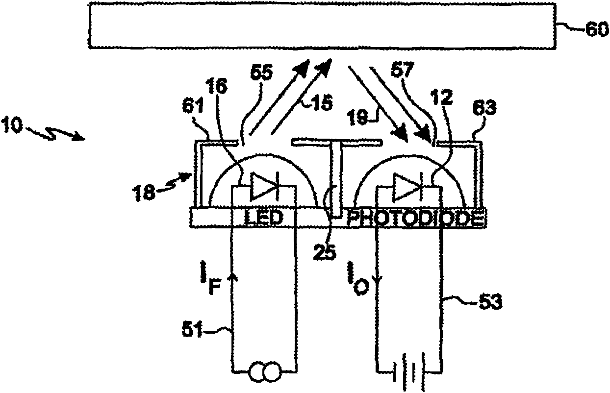
[0025] now refer to Figure 4 , shows an optical proximity sensor 10 comprising a light emitter 16 mounted on a substrate 11 and separated from a light detector 12 by an optically transmissive material 21 which is single-molded Two-part epoxy or transfer molding compound. Such as Figure 4As shown, while light ray 15 is transmitted through material 21, other reflected, diffracted or refracted IR radiation 19 may leak through single mode compound 21 to photodetector 12 and present itself as a photoemitter. Undesired crosstalk or interference between 16 and photodetector 12, thereby degrading the performance of proximity sensor 10.

[0026] Such as Figure 5 As shown, the amount of reflected, diffracted, or refracted IR radiation 19 and unwanted crosstalk or interference between light emitter 16 and light detector 12 is often exacerbated by the presence of window 23, which in some applications The device is provided as part of a portable or other type of electronic device in...


PUM


Abstract

An optical proximity sensor is provided that comprises an infrared light emitter an infrared light detector, a first molded optically transmissive infrared light pass component disposed over and covering the light emitter and a second molded optically transmissive infrared light pass component disposed over and covering the light detector. Located in-between the light emitter and the first molded optically transmissive infrared light pass component, and the light detector and the second molded optically transmissive infrared light pass component is a substantially optically non-transmissive infrared light barrier component. The infrared light barrier component substantially attenuates or blocks the transmission of undesired direct, scattered or reflected light between the light emitter and the light detector, and thereby minimizes optical crosstalk and interference between the light emitter and the light detector.

Description

technical field [0001] Various embodiments of the invention described herein relate to the field of proximity sensors and components, devices, systems and methods related thereto. Background technique [0002] Optical proximity sensors (such as AVAGO TECHNOLOGIES TM HSDL-9100 Surface Mount Proximity Sensor, AVAGO TECHNOLOGIES TM APDS-9101 Integrated Reflective Sensor, AVAGO TECHNOLOGIES TM APDS-9120 Integrated Optical Proximity Sensor and AVAGO TECHNOLOGIES TM APDS-9800 integrated ambient light and proximity sensor) is known. Such sensors typically include an integrated high-efficiency infrared emitter or light source and corresponding photodiode or light detector, and are used in a large number of handheld electronic devices such as cell phones, personal data assistants (PDAs), laptop or portable computers, Portable and handheld devices, coin-operated amusement equipment, industrial automatic machines and equipment, non-contact switches, sanitary automatic machines ...

Claims


Application Information

Patent Timeline
IPC IPC(8): G01D5/34
CPCG01S17/026H03K2017/9455H01L31/173H01L31/167G01S7/4813G01D5/34715H03K17/941H01L33/56H03K2217/94108H01L24/97H01L2224/48091H01L2224/48227H01L2924/14Y10T29/4913G01S17/04H01L2924/00014H01L2924/00
Inventor 詹姆斯·卡斯特罗兰尼·萨拉万南谭维新
Owner AVAGO TECH INT SALES PTE LTD
Why Eureka
Try Eureka