Machine tool

A technology for machine tools and objects, applied in computer control, metal processing mechanical parts, large fixed members, etc., can solve problems such as spindle tilting to one side, unsatisfactory accuracy level of processed workpieces, etc., to prevent the reduction of processing accuracy. Effect

Inactive Publication Date: 2013-07-10
MITSUBISHI HEAVY IND LTD
View PDF2 Cites 2 Cited by
  • Summary
  • Abstract
  • Description
  • Claims
  • Application Information

AI Technical Summary

Problems solved by technology

Thermal deformation of such structures may tilt the spindle to one side and lead to an unsatisfactory level of precision in the machined workpiece

Method used


Image

  • Machine tool
  • Machine tool
  • Machine tool

Examples


Embodiment Construction

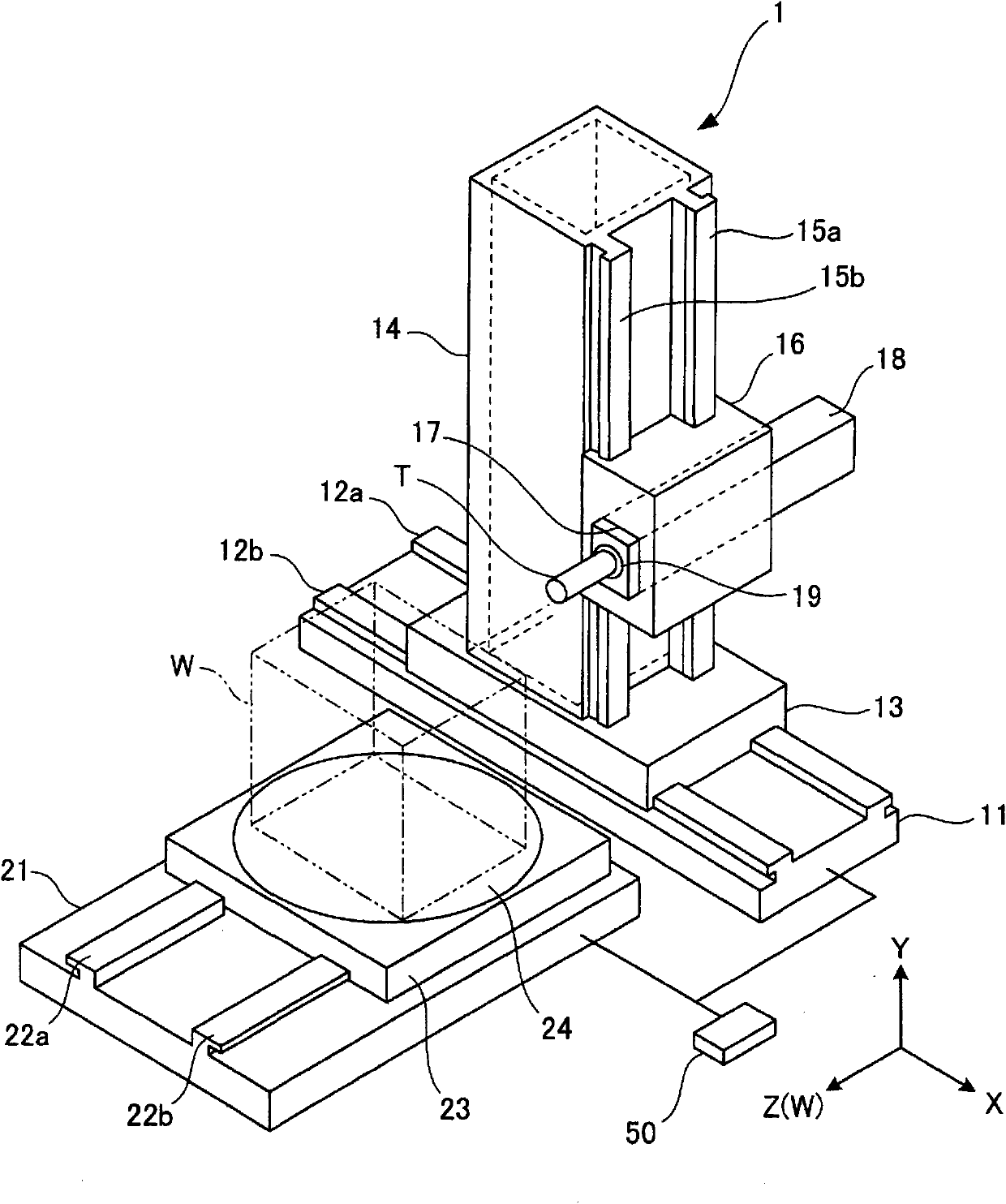
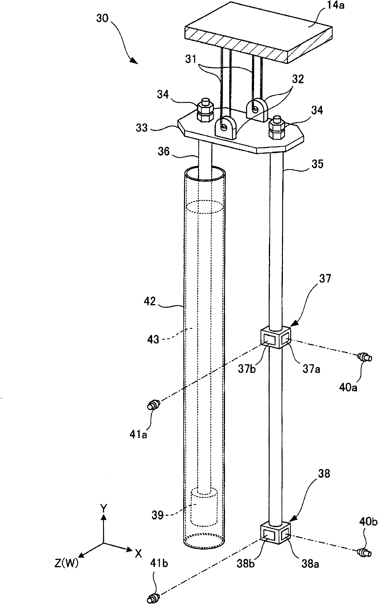
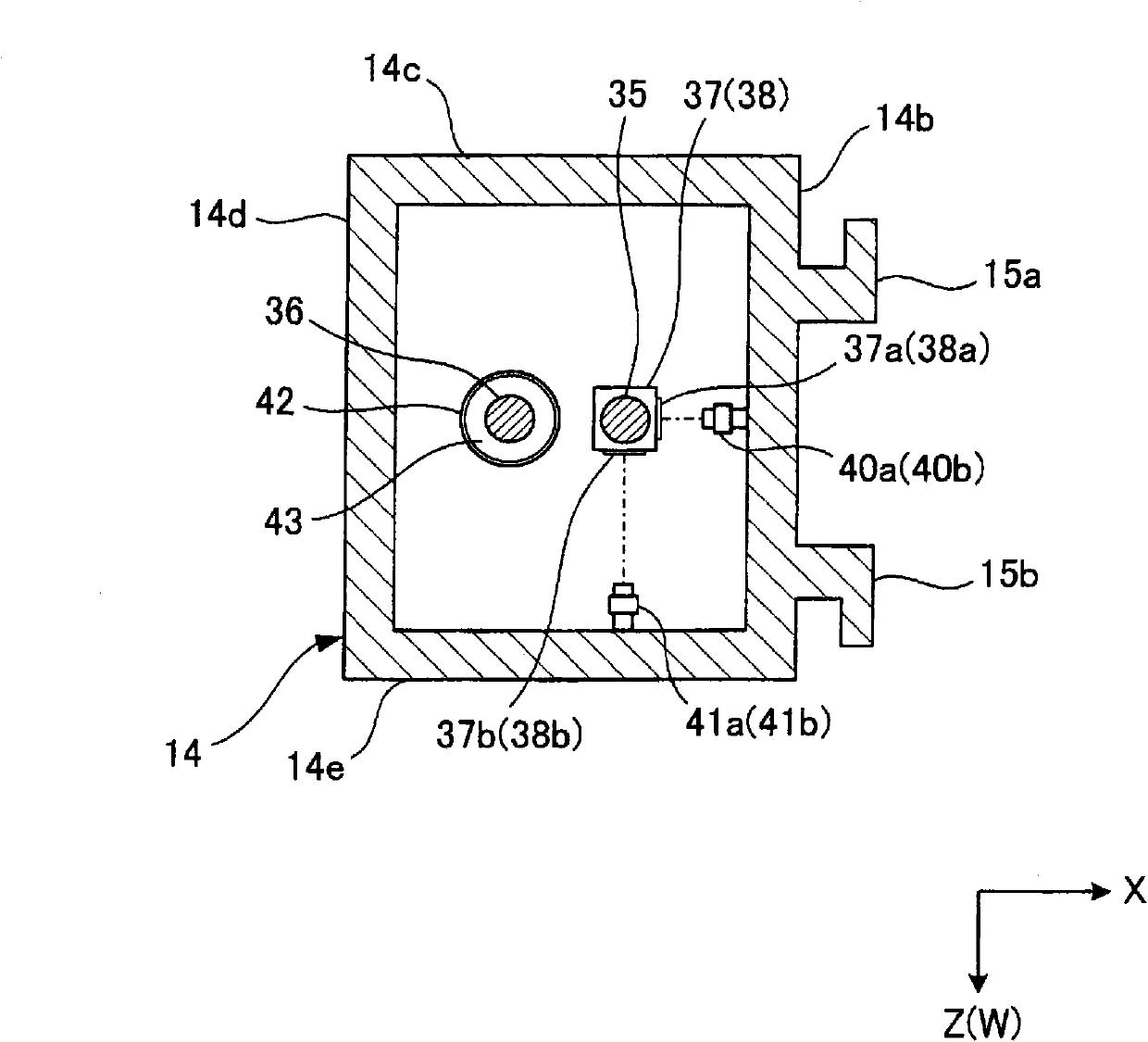
[0048] A machine tool according to an embodiment of the present invention will be described in detail below with reference to the accompanying drawings. figure 1 is a schematic perspective view of a machine tool according to an embodiment of the present invention. figure 2 is an overall configuration diagram illustrating the column deformation detection equipment. image 3 is the cross-sectional view of the column. Figure 4 is a schematic diagram illustrating how the column deforms along the X-axis. Figure 5 is a schematic diagram showing how the column deforms along the Z-axis. In each drawing, directions indicated by X, Y, and Z(W) represent orthogonal three-axis directions, which are orthogonal to each other, and specifically, respectively represent front-rear directions, The vertical direction of the machine tool and the width direction of the machine tool. In addition, an embodiment to be described below is an application of the machine tool according to the presen...


PUM


Abstract

A machine tool in which machining precision can be prevented from lowering even in a case where a column deforms due to movement of a main spindle to each axial direction. A machine tool (1) for machining a work (W) by relatively moving a tool (T) and the work (W) comprises a saddle (16) for rotatably supporting a main spindle (19) to which the tool (T) is removably attached, a column (14) movably provided and movably supporting the saddle (16), and a column deformation detector (30) for detecting deformation of the column (14) caused by movement of at least one of the saddle (16) and the column (14), wherein movement of at least one of the tool (T) and the work (W) is corrected based on the detection result of the column deformation detector (30).

Description

technical field [0001] The present invention relates to a machine tool for processing an object by moving the object and a tool relative to each other. Background technique [0002] Machine tools in recent years have faced an ever-increasing demand for higher machining accuracy. Accuracy in machining performed by a machine tool significantly depends on the geometric accuracy of the machine tool itself, for example: the smoothness of movement of components such as the table on which the workpiece is mounted and the saddle supporting the spindle; the Straightness of movement; parallelism and perpendicularity of movement relative to the spindle centerline. In other words, machining accuracy is determined by the accuracy with which the tool and workpiece are positioned relative to each other when machining is performed. [0003] In addition, in order to obtain high precision when machining workpieces, it is necessary for the machine tool itself to maintain high dimensional acc...

Claims


Application Information

Patent Timeline
Patent Type & Authority Patents(China)
IPC IPC(8): B23Q15/18B23Q1/72B23Q17/22G05B19/404
CPCG05B2219/49186B23Q11/0028B23Q15/18G05B19/404G05B2219/45148B23Q17/22
Inventor 堂丸宏之水田桂司
Owner MITSUBISHI HEAVY IND LTD
Why Eureka
Try Eureka