Rubber cutting machine capable of carrying out precise machining

A technology of precision processing and rubber cutting machine, which is applied in metal processing and other directions, and can solve problems such as difficulty in guaranteeing rubber cutting accuracy, obstruction of staff, and large manual operation errors.

Inactive Publication Date: 2014-11-26
ZHANGJIAGANG HONGLI RUBBER & PLASTIC PROD
View PDF7 Cites 1 Cited by
  • Summary
  • Abstract
  • Description
  • Claims
  • Application Information

AI Technical Summary

Problems solved by technology

The rubber cutting machine in the existing processing technology often requires the staff to manually fix the processing position of the rubber on the rubber guide seat used for rubber cutting; however, in the fixing process, there may be large errors due to manual operation , so it is difficult to guarantee the cutti...

Method used


Image

  • Rubber cutting machine capable of carrying out precise machining
  • Rubber cutting machine capable of carrying out precise machining
  • Rubber cutting machine capable of carrying out precise machining

Examples


Embodiment 1

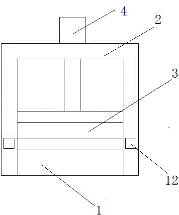
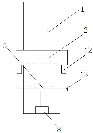
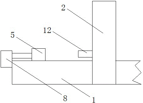
[0023] Such as figure 1 , figure 2 and image 3 A rubber cutting machine capable of precise processing is shown, which includes a rubber guide seat 1 for placing rubber, a frame 2 is arranged in the rubber guide seat, and the opposite end faces of the frame 2 and the rubber guide seat 1 are provided with The rubber cutting knife 3 is controlled by the hydraulic cylinder 4 arranged on the upper end of the frame; in the rubber cutting machine capable of precise processing, the end of the rubber guide seat 1 is vertical to the rubber cutting knife 3 A baffle 5 is provided between the planes; a slide rail 6 is provided at the junction of the upper end surface and the side end surface of the rubber guide seat 1 , and the baffle 5 extends to the inside of the slide rail.

[0024] As an improvement of the present invention, such as Figure 4 As shown, the two ends of the lower end of the baffle plate 5 are provided with pulleys 7 extending to the inside of the slide rail 6 ; the ...

Embodiment 2

[0031] As an improvement of the present invention, two laser range finders 12 are arranged in the frame 2, which are respectively arranged in the frame 2, and are located on the outer parts of the two sides of the side end surface of the rubber guide seat 1; The side end surface of the plate 5 is provided with a distance measuring plate 13 extending vertically outside the side end surface along the length direction of the baffle plate. An electrical connection is adopted between the range finder 12 and the pneumatic cylinder 8 . With the above design, it can make the laser rangefinder effectively measure the distance between the baffle and the frame, and through the pneumatic cylinder electrically connected to it, the baffle can be accurately positioned to the required processing distance, thereby further improving the processing accuracy; At the same time, the above solution avoids the impact on rubber transmission by setting the laser range finder outside the rubber guide se...


PUM

PropertyMeasurementUnit
Lengthaaaaaaaaaa
Lengthaaaaaaaaaa

Abstract

The invention relates to a rubber cutting machine capable of carrying out precise machining. The rubber cutting machine comprises a rubber guide base used for containing rubber, a rack is arranged in the rubber guide base, the end face, opposite to the rubber guide base, of the rack is provided with a rubber cutter, and the rubber cutter is controlled by a hydraulic cylinder which is arranged on the upper end face of the rack. According to the rubber cutting machine capable of carrying out precise machining, a baffle is arranged between the tail end of the rubber guide base and a vertical plane where the rubber cutter is located, a slide rail is arranged at the joint of the upper end face of the rubber guide base and the side end face of the rubber guide base, and the baffle extends into the sliding rail. By means of the technical scheme, rubber can be fixed to the position where the rubber is machined through the baffle which can carry out precise positioning, and therefore machining precision reducing caused by deviation generated when a worker adjusts the rubber machining position can be avoided; meanwhile, due to elasticity of the baffle, the baffle can prevent the rubber cutter from cutting the rubber obliquely when the rubber makes contact with the rubber cutter.

Description

technical field [0001] The invention relates to a processing device, in particular to a rubber cutting machine capable of precise processing. Background technique [0002] Rubber cutting machine is one of the commonly used machinery for rubber cutting. The rubber cutting machine in the existing processing technology often requires the staff to manually fix the processing position of the rubber on the rubber guide seat used for rubber cutting; however, in the fixing process, there may be large errors due to manual operation , so it is difficult to guarantee the cutting accuracy of the rubber, and in most rubber cutting machines, there are often racks around the cutting position of the rubber, which hinders the staff, so it further causes the difficulty of precise positioning of the rubber; in addition, There is a certain potential safety hazard for the staff to operate the rubber below the cutter. Contents of the invention [0003] The technical problem to be solved by th...

Claims


Application Information

Patent Timeline
IPC IPC(8): B26D1/08B26D7/01B26D7/28
Inventor 施春华章炳芳
Owner ZHANGJIAGANG HONGLI RUBBER & PLASTIC PROD
Why Eureka
Try Eureka