Work transfer apparatus

a technology of work transfer and crossbar unit, which is applied in the direction of metal-working feeding device, transportation and packaging, manufacturing tools, etc., can solve the problems of difficult removal of left and right works from dies, and achieve the effect of easy assembly and disassembly of the crossbar uni

Active Publication Date: 2016-06-16
AIDA ENG LTD
View PDF7 Cites 1 Cited by
  • Summary
  • Abstract
  • Description
  • Claims
  • Application Information

AI Technical Summary

Benefits of technology

[0016]In order to prevent deterioration of machining accuracy due to an inclination of a press slide, it is effective to reduce an imbalance of a load applied to a press machine at the time of pressing in general.

Problems solved by technology

In such case, as the prior art, when transfer devices which tilt the right and left works in the same direction are used, it is difficult to remove the left and right works from dies respectively and place the left and right works into left and right dies of next press machine respectively with suitable posture corresponding to the dies in left and right reversed.

Method used


Image

  • Work transfer apparatus
  • Work transfer apparatus
  • Work transfer apparatus

Examples


Embodiment Construction

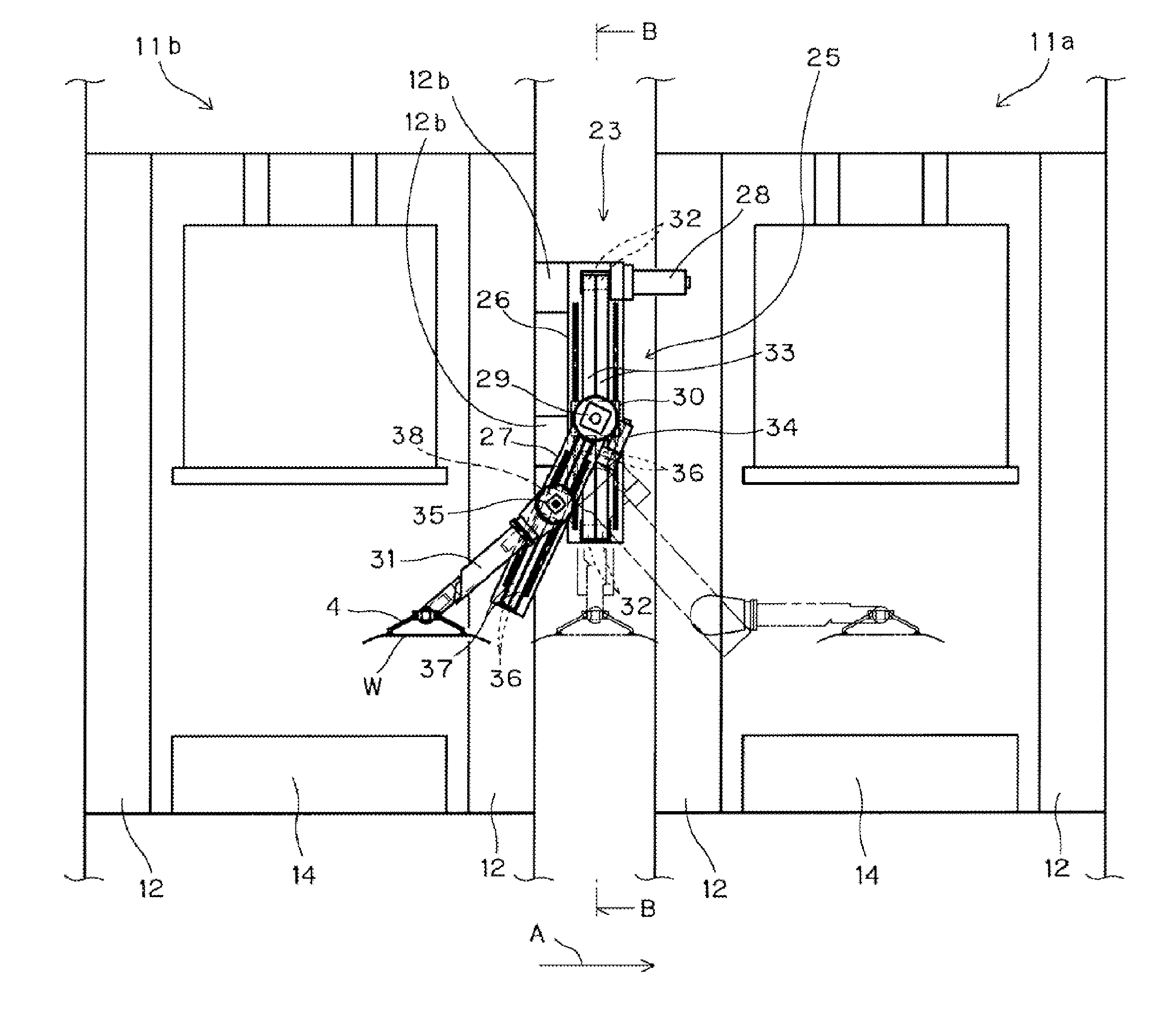
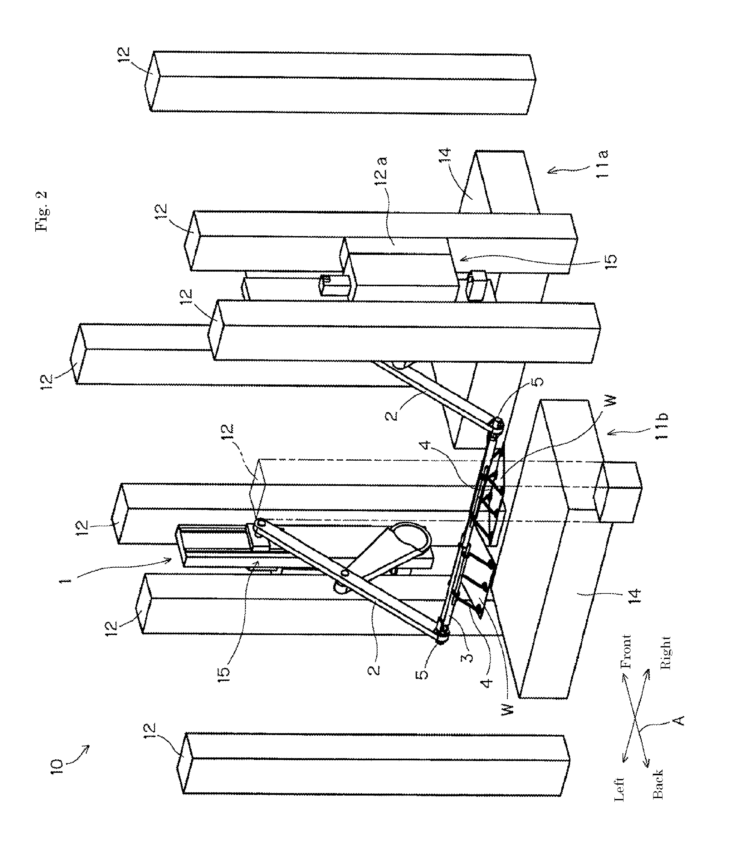
[0060]First, the outline of the press line using the work transfer apparatus of the present invention is described using FIG. 2.

[0061]In addition, an arrow A in FIG. 2 indicates a direction in which the work W is conveyed.

[0062]And that the conveying direction of the work W is referred to as the front and rear directions. The direction in which the arrow A directs front (or downstream), and the work W is conveyed from rear to front.

[0063]Further, the left and right directions are based on the left hand side and right hand side when one faces to the front direction.

[0064]Two press machines 11a, 11b shown in FIG. 2, are disposed in a transfer line 10.

[0065]The front press machine is shown in “a” of subscript, the rear is shown in “b”.

[0066]Between these press machines 11a, 11b, a work transfer apparatus 1 of the present invention is located.

[0067]Further the number of press machines, may be three or more.

[0068]Moreover instead of the press machine, other machines such as a punching de...


PUM


Abstract

To provide a work transfer apparatus which can transfer works at high speed with controlling respectively the posture of the right and left of works. The work transfer apparatus includes an arm moving back and forth between machines in order to transfer work(s), a crossbar coupled to the arm, and a pair of right and left work holding devices provided at the left and right sides of the crossbar and tilt drive devices being provided on the arm, respectively controlling the work holding devices to rotate around an axis of a longitudinal direction of the crossbar.

Description

CROSS REFERENCE TO RELATED APPLICATION[0001]The present application is a Continuation application of U.S. Ser. No. 13 / 894,066 filed May 14, 2013, which claims priority to Japanese patent applications No. 2012-111831 filed on May 15, 2012. The subject matter of each is incorporated herein by reference in entirety.TECHNICAL FIELD[0002]The present invention relates to a work transfer apparatus which transfers a work.[0003]For further details, it relates to the work transfer apparatus which transfers the work between adjacent machines by swinging arm(s) thereof.DESCRIPTION OF THE RELATED ART[0004]There is a conventional prior art that, in case of conveying plural works in parallel, can tilt (tilting) the works in the same direction by rotating the works in the same direction around an axis of a crossbar.[0005]In Patent Document 1, a work conveying device (hereinafter, conveying device) is disclosed.[0006]The conveying devices are extended on both sides of a conveying line to convey the ...

Claims


Application Information

Patent Timeline
Patent Type & Authority Applications(United States)
IPC IPC(8): B21D43/05B21D43/10
CPCB21D43/105B21D43/052B21D43/00
Inventor TAKEDA, KEISUKE
Owner AIDA ENG LTD
Why Eureka
Try Eureka