Personal triphibious transport tool

A vehicle and airframe technology, applied in the field of small vehicles

Inactive Publication Date: 2011-01-12
杨朝习
View PDF7 Cites 5 Cited by
  • Summary
  • Abstract
  • Description
  • Claims
  • Application Information

AI Technical Summary

Problems solved by technology

[0003] The purpose of the present invention is to provide a personal amphibious vehicle, to overcome the use limitations of existing personal vehicles, and to solve the problem of complex structure and volume of composite vehicles. Problems such as large size, high "dead weight", low safety and incapability of vertical / short take-off and landing

Method used


Image

  • Personal triphibious transport tool
  • Personal triphibious transport tool
  • Personal triphibious transport tool

Examples


Embodiment 1

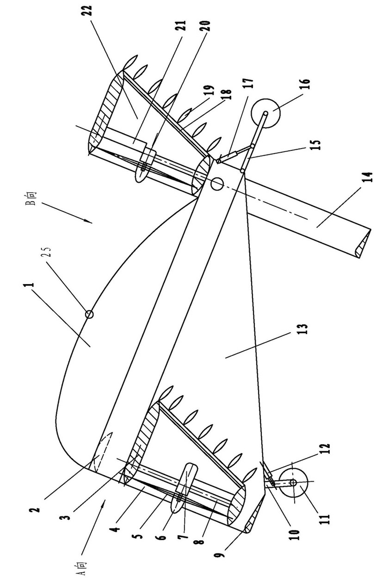
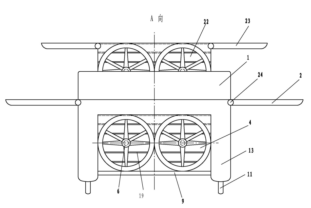
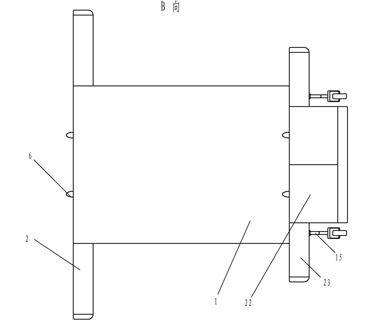
[0024] Such as figure 1 , figure 2 As shown, the personal amphibious vehicle of the present invention includes a body 1 with upper and lower surfaces, whose shape is designed according to the principle of aerodynamics. The sheet body 13, the side surface of the sheet body 13 is a right triangle with the hypotenuse at the bottom. The two sheet bodies 13 are fixedly connected with the body 1 . A front hydrofoil 9 is connected between the front end bottoms of the two sheet bodies 13 . Both ends of the front hydrofoil 9 can be fixedly connected to the inner surfaces of the two sheet bodies 13; a set of flipping mechanisms can also be respectively arranged inside the two sheet bodies 13 to separate the two ends of the front hydrofoil 9 Connected with the two reversing mechanisms, a reversible upper and lower interchangeable front hydrofoil is formed to meet different requirements on land and underwater. Also be provided with front landing gear 10 and front landing gear retrac...

Embodiment 2

[0030] Such as Figure 5 As shown, the main structure of this embodiment is basically the same as that of Embodiment 1, except that the front duct fans 4 arranged at the bottom of the front end of the body 1 and between the two bodies 13 are three arranged side by side, and the rear duct fans 22 are also arranged The ones are three side by side. The foldable front wing 2 is arranged on the front end of the body 1 , and the foldable rear wing 23 is arranged on the shell outer surfaces of the two rear ducted fans on both sides of the three rear ducted fans 22 . Of course, the quantity of the rear ducted fan 22 may not be consistent with the quantity of the front ducted fan 4, but it should be less than the quantity of the front ducted fan 4, so that the U-shaped hydrofoil mounted on the rear end of the body 1 can be turned up smoothly .

[0031] In this embodiment, since the number of front and rear ducted fans increases, the propulsion power is increased, so the passenger cap...

Embodiment 3

[0033] Such as Figure 6 , Figure 7 As shown, the main structure of this embodiment is basically the same as that of Embodiment 1. The main difference is that the front duct fan 4 and the rear duct fan 22 are only provided with one, thereby forming a personal amphibious with the lightest weight and the simplest structure. The second is that the setting of the front wing has been canceled; the third is that the rear wing 23 has been refitted from the ducted housing of the rear ducted fan 22 to both sides of the rear of the body 1; the fourth is that the sheet body 13 has been changed from a fixed connection to In order to be hinged on the bottom surface of the body 1, a hydraulic control mechanism is provided inside the body 1 to control the outward turning of the panels, thereby forming an amphibious vehicle in which the panels can be turned outwards.

[0034] Because the sheet body 13 in the present embodiment is a kind of flexible connection form that can be turned sideway...


PUM


Abstract

The invention relates to a personal triphibious transport tool comprising an airframe, a cabin and lamellar bodies, wherein the bottom of the front end of each lamellar body is provided with a front undercarriage and a front undercarriage controlling device; the rear end of the airframe is provided with a rear undercarriage and a rear undercarriage controlling device; the front end of the bottom of the airframe is provided with a front ducted fan perpendicular to the airframe, wherein the front end of the bottom of the airframe is positioned between the two lamellar bodies; the top surface of the rear end of the airframe is provided with a rear ducted fan perpendicular to the airframe; the front ducted fan and the rear ducted fan are respectively provided with a guide plate, a diffuser grid, a guide plate deflection control mechanism and a diffuser grid deflection control mechanism; both sides of the rear end of the airframe or both sides of the rear ducted fan are articulated with rear airfoils; the rear end of the airframe is articulated with a U-shaped hydrofoil. The invention adopts a peculiar overturned airframe type and thrust deflection type mixed configuration structure and meets the requirements of outing of people through the overall transition of water, land and air.

Description

technical field [0001] The invention relates to a small-sized personal vehicle, in particular to a personal amphibious vehicle. Background technique [0002] At present, some amphibious vehicles for amphibious use or land and air use have been practically used. These amphibious vehicles expand the application field of ordinary vehicles and provide certain convenience for use. However, the structures of these amphibious vehicles are generally relatively complicated, occupy a large area, and have the problems of high "dead weight" and low safety. Existing designs of amphibious means of transportation cannot be put into practical application because of their structures are not reasonable enough, and cannot effectively solve the traffic problems of water, land and air amphibiously at the same time, and also cannot realize vertical / short-distance take-off and landing. Contents of the invention [0003] The purpose of the present invention is to provide a personal amphibious v...

Claims


Application Information

Patent Timeline
Patent Type & Authority Applications(China)
IPC IPC(8): B60F5/00
Inventor 杨朝习
Owner 杨朝习
Why Eureka
Try Eureka