Self-starting equipment of vertical axis wind turbine
A wind turbine and self-starting technology, which is applied to wind turbines, wind turbines at right angles to the wind direction, machines/engines, etc., can solve the problems of reducing wind energy utilization efficiency and poor self-starting performance, and achieve the effect of improving wind energy utilization efficiency.
- Summary
- Abstract
- Description
- Claims
- Application Information
AI Technical Summary
Problems solved by technology
Method used
Image
Examples
Embodiment 1
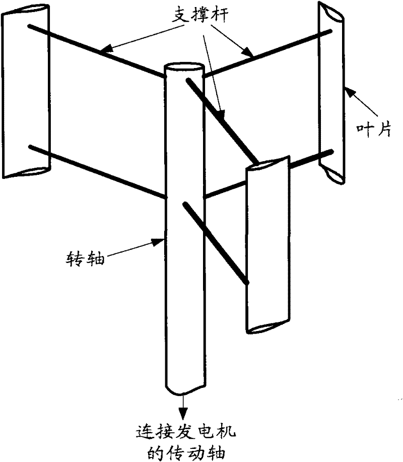
[0040] see Figure 4 , Figure 4 It is a schematic structural diagram of a self-starting device for a vertical axis wind turbine provided in Embodiment 1 of the present invention. Such as Figure 4 As shown, the self-starting device may include:
[0041] A rotating shaft (1), a blade (2) and a support rod (3);
[0042] Wherein, the blade (2) is a straight blade; the cross-section of the support rod (3) is in the shape of a concave front and a pointed rear;
[0043] Wherein, the number of blades (2) is at least two, and at least one support rod (3) is connected between each blade (2) and the rotating shaft (1);
[0044] Wherein, the lower end of the rotating shaft (1) is connected to the transmission shaft of the generator to realize torque transmission and wind energy conversion.
[0045] In Embodiment 1 of the present invention, the blade (2) may be a whole blade, or may be formed by connecting multiple blades.
[0046] In Embodiment 1 of the present invention, each sup...
Embodiment 2
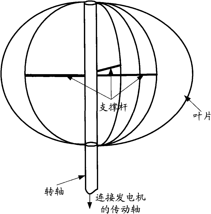
[0056] see Figure 7 , Figure 7 It is a structural schematic diagram of another self-starting device for a vertical axis wind turbine provided in Embodiment 2 of the present invention. Such as Figure 7 As shown, the self-starting device may include:
[0057] A rotating shaft (1), a blade (2) and a support rod (3);
[0058] Wherein, the blade (2) is in the shape of a crescent moon; the cross section of the support rod (3) is in the shape of a concave front and a pointed rear;
[0059] Wherein, both ends of each blade (2) are fixedly connected to the rotating shaft (1), and at least one support rod (3) is connected between the inner edge of each blade (2) and the rotating shaft (1);
[0060] Wherein, the lower end of the rotating shaft (1) is connected to the transmission shaft of the generator to realize torque transmission and wind energy conversion.
[0061] In the second embodiment of the present invention, the blade (2) may be a whole piece of curved blade, or may be...
PUM
 Abstract
Description
Claims
Application Information
 - R&D
- Intellectual Property
- Life Sciences
- Materials
- Tech Scout
- Unparalleled Data Quality
- Higher Quality Content
- 60% Fewer Hallucinations
Browse by: Latest US Patents, China's latest patents, Technical Efficacy Thesaurus, Application Domain, Technology Topic, Popular Technical Reports.
© 2025 PatSnap. All rights reserved.Legal|Privacy policy|Modern Slavery Act Transparency Statement|Sitemap|About US| Contact US: help@patsnap.com


