Actuator part inner bore combined seal ring component shaping method

A combined seal and actuator technology, applied in the direction of assembly machines, metal processing equipment, manufacturing tools, etc., can solve the problems of seal ring damage, seal damage, and low product assembly survival rate, so as to improve the survival rate and eliminate residual The effect of deformation

Active Publication Date: 2011-01-19
FLIGHT AUTOMATIC CONTROL RES INST
View PDF5 Cites 0 Cited by
  • Summary
  • Abstract
  • Description
  • Claims
  • Application Information

AI Technical Summary

Problems solved by technology

The sealing ring in the combined sealing ring assembly is a special-shaped fluoroplastic sealing ring, which is an important part that determines the sealing effect. During the process of installing the fluoroplastic sealing ring into the sealing groove, there must be local deformation. Large, after assembly, it is easy to make the residual deformation of the fluoroplastic sealing ring difficult to eliminate, and may even cause damage to the sealing ring
The above problems may lead to serious failures such as oil leakage or seal damage
Using traditional mechanical plastic shaping, the survival rate of product assembly is less than 80%

Method used


Image

  • Actuator part inner bore combined seal ring component shaping method
  • Actuator part inner bore combined seal ring component shaping method
  • Actuator part inner bore combined seal ring component shaping method

Examples


Embodiment 1

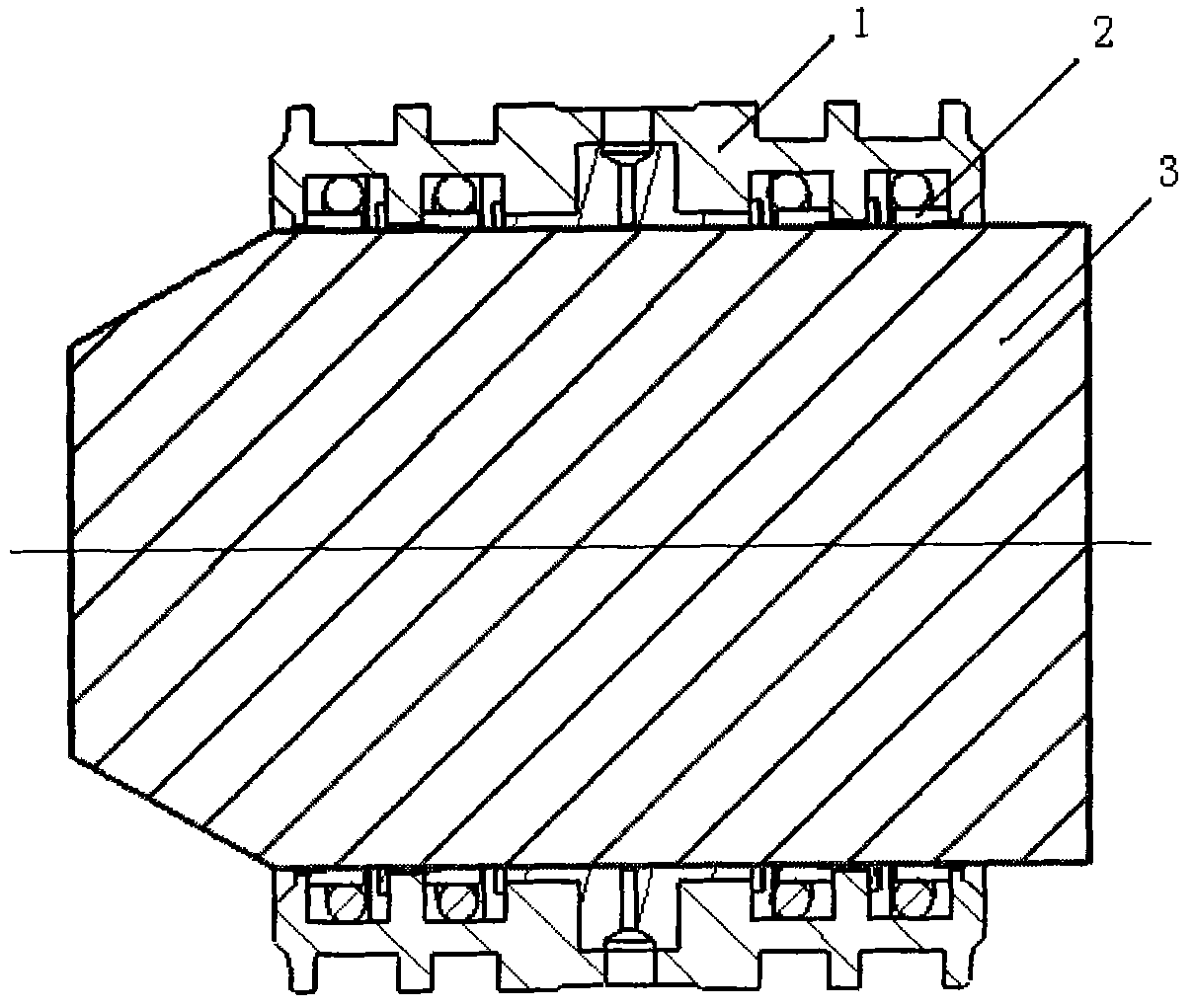
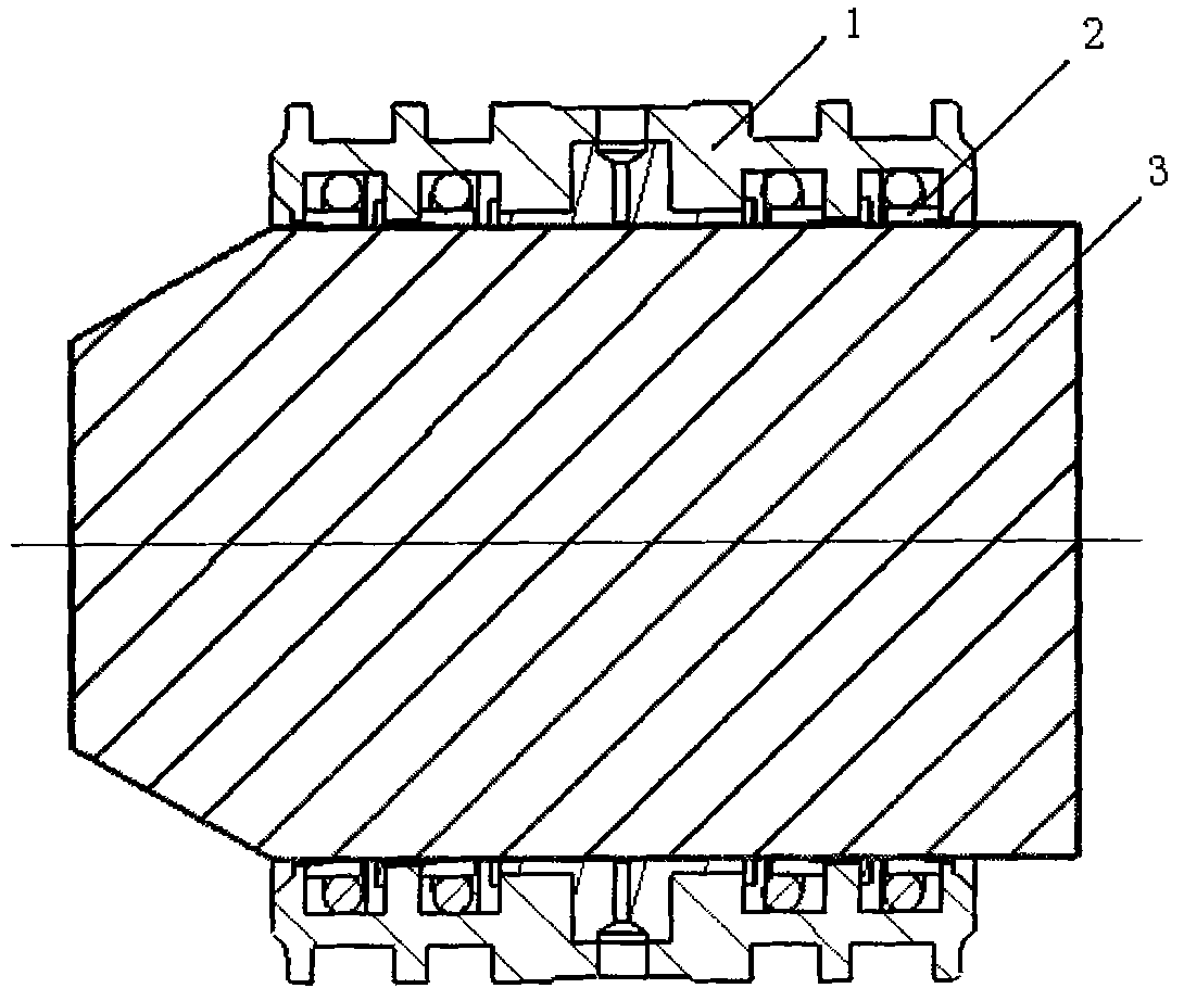
[0010] Embodiment 1, shaping the separation bush combined sealing ring assembly. Install the separation bush sealing ring assembly 2 with the fluoroplastic sealing ring into the sealing groove of the inner hole of the separation bush 1 to form the separation bush assembly, and then insert the separation bush shaping mandrel 3 into the inner hole of the separation bush assembly , put the separator liner assembly into an oven, raise the temperature to 65°C, take it out after keeping it warm for 2 hours, and let it cool down to room temperature naturally. After assembly, the sealing performance is good.

Embodiment 2

[0011] Embodiment 2, shaping the separation bush combined sealing ring assembly. Install the separation bush sealing ring assembly 2 with the fluoroplastic sealing ring into the sealing groove of the inner hole of the separation bush 1 to form the separation bush assembly, and then insert the separation bush shaping mandrel 3 into the inner hole of the separation bush assembly , Put the separator liner assembly into an oven, raise the temperature to 70°C, take it out after keeping it warm for 1.5 hours, and let it cool down to room temperature naturally. After assembly, the sealing performance is good.

Embodiment 3

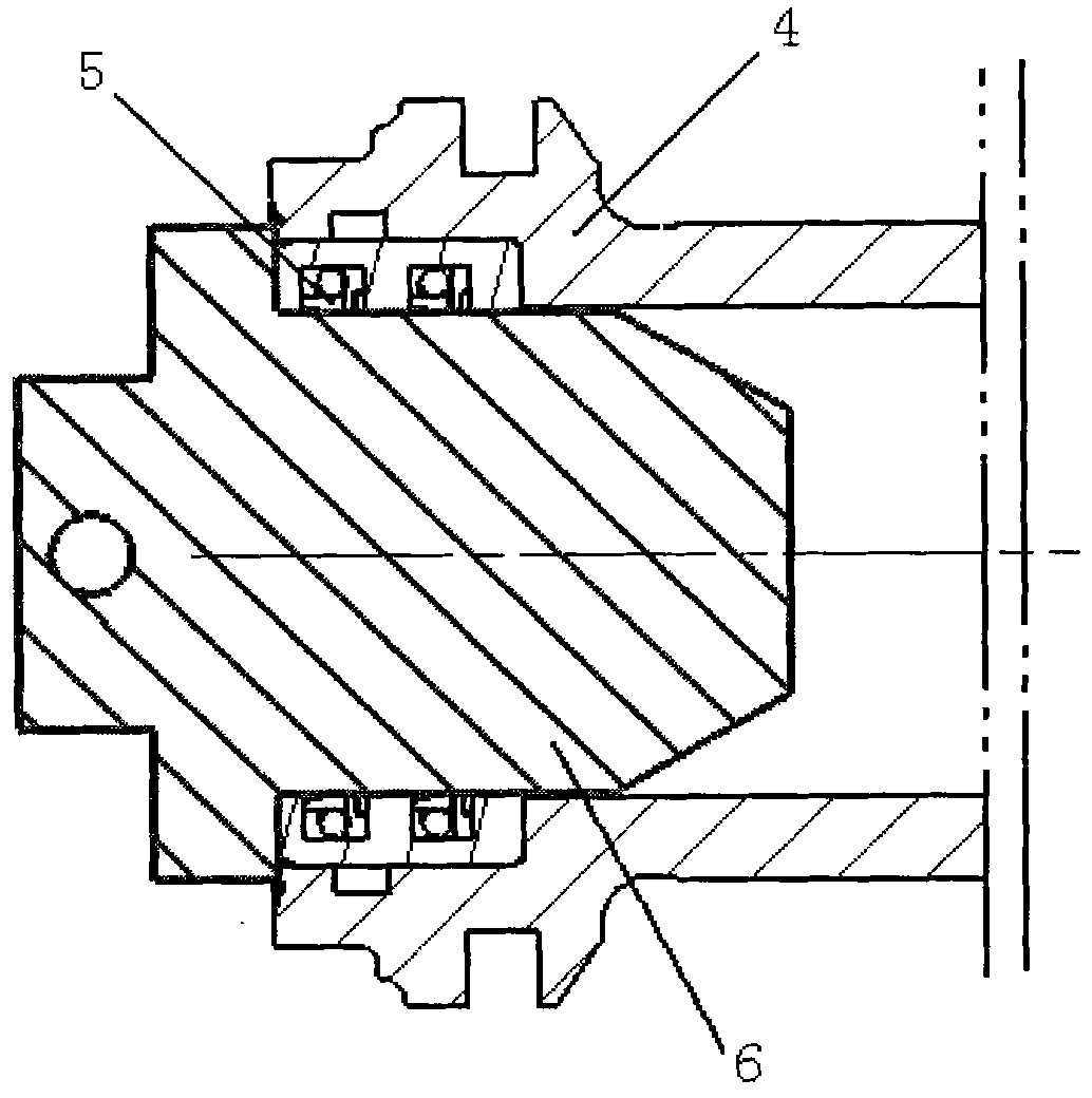
[0012] Embodiment 3, shaping the combined sealing ring assembly of the main piston. Install the main piston seal ring assembly 5 with the fluoroplastic sealing ring in the sealing groove of the inner hole of the main piston 4 to form the main piston assembly, then insert the main piston shaping mandrel 6 into the inner hole of the main piston assembly, and place the main piston assembly Put it in an oven, raise the temperature to 75°C, keep it warm for 1 hour, take it out, and let it cool down to room temperature naturally. After assembly, the sealing performance is good.


PUM


Abstract

The invention belongs to assembly technology, and relates to improvement on an actuator part inner bore combined seal ring component shaping method. The method comprises a mechanical shaping step, and is characterized in that: a dividing bushing component or a main piston component is subjected to heat treatment, heated in an oven to 70+/-5 DEG C, kept at the temperature of 70+/-5 DEG C for 1 to 2 hours, taken out, and naturally cooled to room temperature. The method has the advantages of eliminating residual deformation of the mechanically shaped fluoroplastic seal ring, and improving the survival rate of product assembly.

Description

technical field [0001] The invention belongs to the assembly technology, and relates to the improvement of the shaping method of the combined seal ring assembly in the inner hole of the actuator part. Background technique [0002] In the large-scale precision actuator with double redundancy, in order to reduce the friction force and improve the service life, before assembly, the combined sealing ring assembly in the inner hole of the actuator part needs to be mechanically reshaped. The actuator part is either the spacer bush or the main piston. The method of the mechanical shaping step is to install the combined seal ring assembly of the separation bush or the combined seal ring assembly of the main piston into the seal groove of the inner hole of the separation bush or the seal groove of the inner hole of the main piston to form the separation bush assembly or the main piston. Piston assembly. Then insert the separation bush shaping mandrel or the main piston shaping mand...

Claims


Application Information

Patent Timeline
Patent Type & Authority Applications(China)
IPC IPC(8): B23P21/00
Inventor 朱朝锋黄玖琦
Owner FLIGHT AUTOMATIC CONTROL RES INST
Why Eureka
Try Eureka