Farmland in-situ soil leaching solution collector and using method thereof

A technology for drenching solution and in-situ soil, which is applied to the field of in-situ soil drench solution collectors in farmland, can solve the problems of inconvenient operation, high construction cost, large engineering amount, etc., and achieves simple shape design, guaranteed reliability, and small engineering amount. Effect

Inactive Publication Date: 2011-01-19
INST OF SOIL & FERTILIZER SHANDONG ACAD OF AGRI SCI
View PDF5 Cites 26 Cited by
  • Summary
  • Abstract
  • Description
  • Claims
  • Application Information

AI Technical Summary

Problems solved by technology

[0006] Although the invention patent with the patent publication number CN101246156A and the name "In-Situ Monitoring Device for Farmland Underground Leaching" has the advantages of simple and fast sampling, it also has obvious shortcomings: (1) The amount of work is relatively large and the cost is high. Waterproof cement walls are built inside the pit; (2) The leaching device occupies a large area in the middle of the farmland, which is not conducive to the conventional farming of the farmland; (3) When taking leaching water samples, it is necessary to go down to the pit for extraction, which is inconvenient to operate

Method used


Image

  • Farmland in-situ soil leaching solution collector and using method thereof
  • Farmland in-situ soil leaching solution collector and using method thereof
  • Farmland in-situ soil leaching solution collector and using method thereof

Examples


Embodiment 1

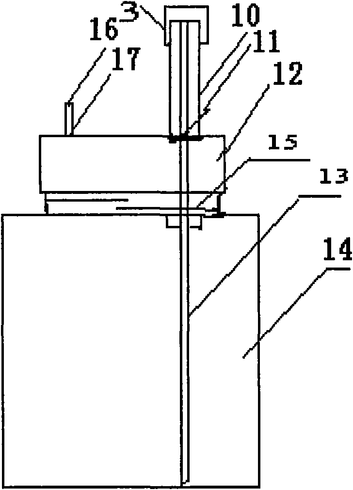
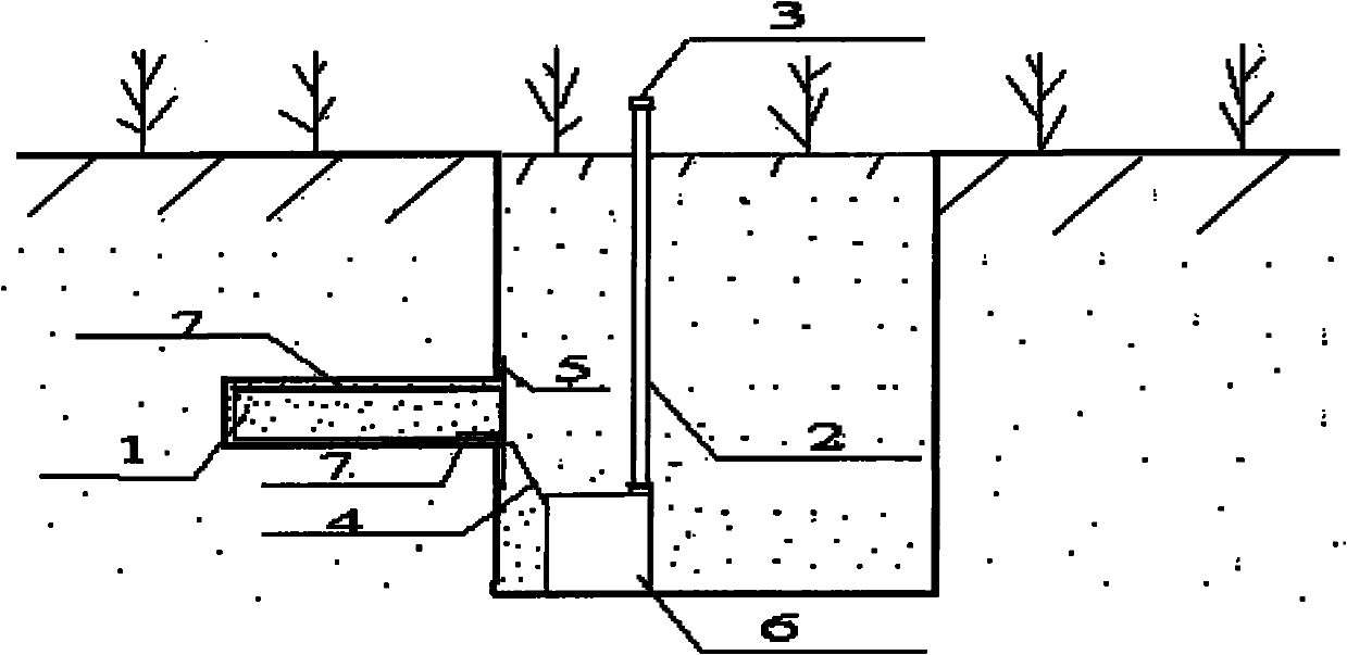
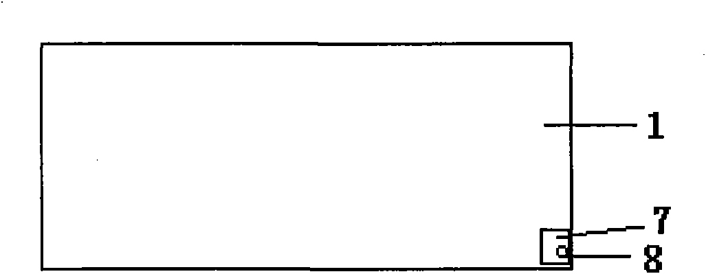
[0034] Embodiment 1 of the present invention is attached Figure 1-4 As shown, it is composed of a leaching pan 1, a connecting pipe 4, a liquid collector 6 and a suction pipe 2. It is characterized in that the leaching pan 1 is an open rectangular water-tight container, and the bottom of the leaching pan 1 is located at the corner. A water outlet, a water nozzle is fixed on the water outlet, and a layer of nylon mesh 7 is covered on the water outlet 8 in the leaching tray 1; There are silk lines 15 on the barrel 14 and the barrel cover 12, and the barrel cover 12 can be screwed tightly on the drum 14 to seal it; the barrel cover 12 has a water inlet 17 and a water outlet 11, and the water inlet nozzles are respectively fixed. 16 and the water nozzle 10, the water nozzle 9 on the water outlet 8 of the leaching plate 1 is connected with the water inlet nozzle 16 on the bucket cover 12 through the connecting pipe 4; the water nozzle 10 on the bucket cover 12 is connected to the ...

Embodiment 2

[0041] Embodiment 2 of the present invention is the same as Embodiment 1, except that the length, width, and height of the leaching tray 1 are respectively 70 cm, 50 cm, and 8 cm; the volume of the drum 14 is 40 L; the inner suction pipe 13 The length is 150cm.

Embodiment 3

[0043] A method for using the above-mentioned in-situ soil leaching solution collector, the steps are as follows:

[0044] (1) Select the central location of the Daejeon experimental plot, determine a horizontal square area with a length of 1m and a width of 1m on the surface, and start digging a pit vertically downward; dig a pit with a depth of 1.3m, and keep the surrounding area of ​​the pit Vertical leveling, the excavated soil should be stacked in layers to facilitate backfilling according to the original soil structure;

[0045] (2) Dig an inner pit horizontally at a depth of 100 cm from the ground surface on one elevation of the pit, with a height, depth, and width slightly greater than the height, width, and length of the leaching plate, so as to ensure that the upper and lower surfaces of the inner pit are smooth;

[0046] (3) Lay the quartz sand on the leaching tray. The thickness of the quartz sand is slightly lower than the height of the leaching tray. After coveri...


PUM

PropertyMeasurementUnit
lengthaaaaaaaaaa

Abstract

The invention discloses a farmland in-situ soil leaching solution collector and a using method thereof, belonging to the field of soil monitoring technology. The collector is composed of a leaching tray, a connecting pipe, a solution collector and a water pumping pipe; when the device is used, a pit is firstly dug and followed by digging an inner pit inside the pit, the dug inner pit is plugged with the leaching tray filled with quartz sand, the connecting pipe and the water-pumping pipe are connected properly, and soil is then gradually backfilled and tamped layer by layer. Watering is performed many times to restore the soil in the pits basically, thus the solution collector can collect the leaching solution of farmland in-situ soil above the leaching tray. The device according to the invention has simple appearance design, small workload for installation and embedment and easy operation. After the device is installed, only the water-pumping pipe thereof is exposed on the ground, thereby taking up no farmland and causing no influence to routine farming.

Description

technical field [0001] The invention relates to an in-situ soil leaching solution collector for farmland and its use method, which belongs to the technical field of soil monitoring, and is particularly suitable for monitoring the influence of nutrients such as nitrogen and phosphorus and the migration of pesticides in soil on groundwater, especially for maintaining farmland Under the condition of the original soil, in-situ monitoring is realized, which reduces the difficulty of sampling, and the whole sampling process is simple and accurate. Background technique [0002] Fertilizers make an important contribution to world food production. According to the statistics of the Food and Agriculture Organization of the United Nations, fertilization in developing countries can increase the yield of food crops by 35% to 57%, and the total output by 30% to 50%. At present, most of the cultivated land in my country needs to be supplemented with nitrogen, more than 1 / 2 of the cultivat...

Claims


Application Information

Patent Timeline
Patent Type & Authority Applications(China)
IPC IPC(8): G01N1/10
Inventor 张英鹏孙明李彦王萍刘兆辉高新昊
Owner INST OF SOIL & FERTILIZER SHANDONG ACAD OF AGRI SCI
Why Eureka
Try Eureka