Electrifying control system

A technology of power generation control and power-on time, which is applied in electrical control, engine control, machine/engine, etc., and can solve problems such as increased engine rotation fluctuations

Active Publication Date: 2013-06-19
DENSO CORP
View PDF4 Cites 0 Cited by
  • Summary
  • Abstract
  • Description
  • Claims
  • Application Information

AI Technical Summary

Problems solved by technology

As a result, the rotational fluctuation of the engine may conversely increase

Method used


Image

  • Electrifying control system
  • Electrifying control system
  • Electrifying control system

Examples


Embodiment Construction

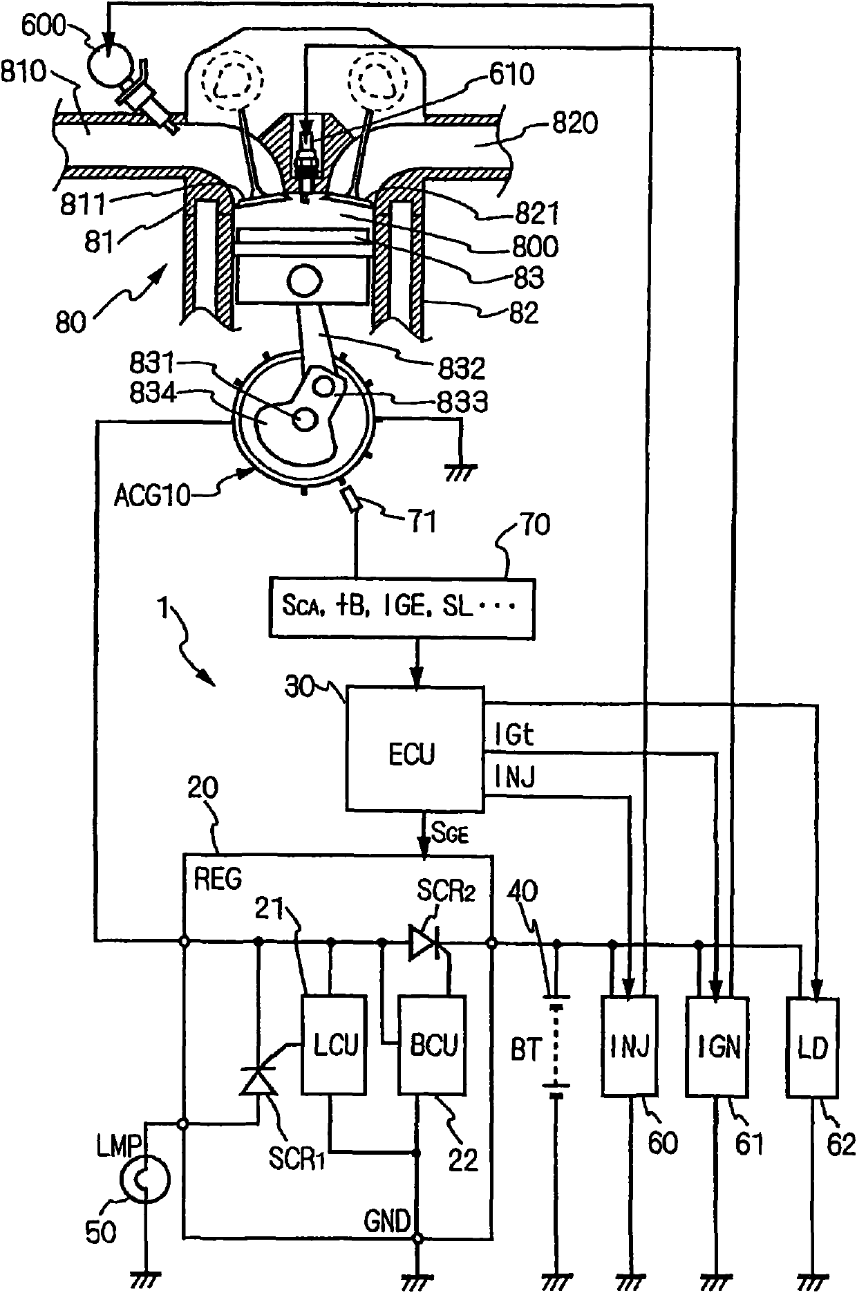
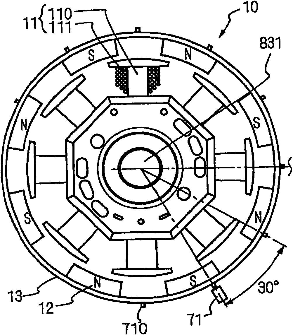
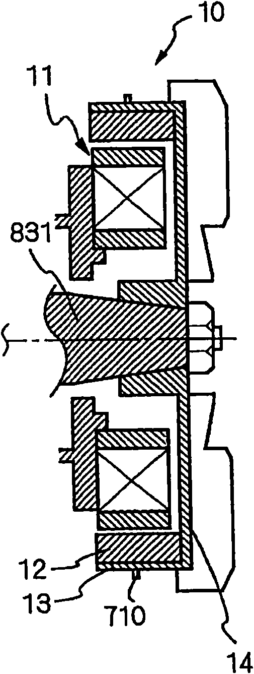
[0024] The present invention is applicable to an alternator generator (ACG) 10 coupled to a crankshaft 831 of an internal combustion engine 80 and thereby rotated by rotation of the crankshaft 831 to generate alternating current. In particular, the present invention is suitable for stabilizing the driving of the fuel injection device 60 and the ignition device 61 against voltage fluctuations of the battery 40 charged by the ACG 10 in the engine 80 having the power generation control device 20 by setting the The permanent magnet 12 serves as a permanent magnet synchronizing the ACG 10 for the field of the rotor 13 , thereby using the generating torque generated in the ACG 10 for suppressing the rotation fluctuation of the crankshaft 831 .

[0025] According to the energization control system 1 of the present invention, the predetermined crank angle CA detected by the crank angle detection unit in the combustion stroke s The timing of (for example, immediately after the burst st...


PUM


Abstract

The invention relates to an electrifying control system, which comprises an engine, a generator, a generating control device, batteries, a crank corner detecting device, a generating control method confirming device, a battery voltage detecting device and a jet electrifying time confirming device. The system controls the electrification of a fuel jetting device and an igniting device from the batteries. The generating control device is arranged for controlling the generation of the generator so as to utilize the generating torque generated by the generator to limit the rotating vibration of acrank shaft. The control method confirming device is arranged for confirming the generating mode based on the crank shaft rotating speed at a preset crank corner detected by the crank corner detecting device. The voltage detecting device is arranged for detecting the battery voltage at a jet determined point. The electrifying time confirming device is arranged for forecasting the voltage at a driving point of the fuel jetting device based on the voltage and generating mode and for confirming the starting time and the ending time for electrifying the jetting device based on the forecasted voltage at the driving point of the fuel jetting device.

Description

field of invention [0001] The present invention generally relates to an energization control system for suppressing rotational fluctuation of an engine having a power generation control device that controls power generation torque of a generator coupled to a crankshaft of an internal combustion engine. In particular, the present invention is suitable for stabilizing the drive of the fuel injection device and the ignition device against fluctuations in the voltage of the battery charged by the generator. Background technique [0002] In the combustion cycle of the internal combustion engine, the engine torque becomes large in the combustion stroke, and the engine torque is set to be small from the exhaust stroke to the compression stroke. In an internal combustion engine whose crankshaft is coupled to a generator, the power generation torque generated at the time of power generation is applied in a direction to suppress the rotational speed of the engine so that the engine to...

Claims


Application Information

Patent Timeline
Patent Type & Authority Patents(China)
IPC IPC(8): F02D29/06F02D43/00
Inventor 土井真
Owner DENSO CORP
Why Eureka
Try Eureka