Lock device for card connector and card connector having the same

A technology for locking devices and card inserts, which is applied to parts of connecting devices, cooperating devices, coupling devices, etc., and can solve the problem of deformation of the locking spring 19, incomplete fit, and inability to engage the protruding part 21 and the recessed part 16 or disengagement

Active Publication Date: 2011-01-26
SMK CO LTD
View PDF1 Cites 3 Cited by
  • Summary
  • Abstract
  • Description
  • Claims
  • Application Information

AI Technical Summary

Problems solved by technology

[0009] (2) When the memory card 11 is embedded in the housing 10, if it is directly extracted (in the present invention, the so-called "direct extraction" refers to the method of directly extracting without using the normal method of first pushing and then extracting) memory card 11, the locking spring 19 may be deformed, and the subsequent fit may not be complete.
[0010] (3) When inserting or extracting the memory card 11, the free end 22 of the locking spring 19 is squeezed toward the opening 23 side. Therefore, due to repeated insertion and extraction, the card locking force is insufficient, or if it is set to be strong on the contrary, the locking spring 19 may be damaged. will be deformed, and proper engagement or disengagement of the protruding portion 21 and the recessed portion 16 cannot be achieved

Method used


Image

  • Lock device for card connector and card connector having the same
  • Lock device for card connector and card connector having the same
  • Lock device for card connector and card connector having the same

Examples


Embodiment 1

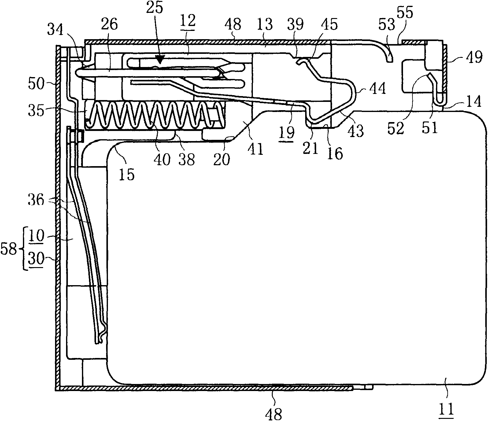
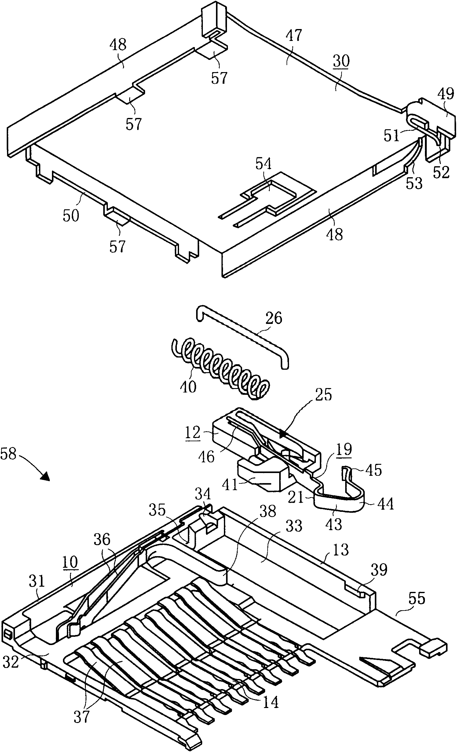
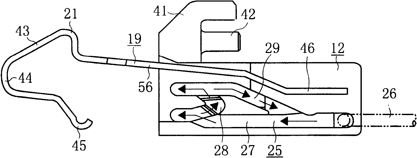
[0070] refer to Figure 1 to Figure 6 Embodiment 1 of the locking device for a card insert of the present invention will be described.

[0071] like figure 1 and figure 2 As shown, the housing 10 and the metal cover 30 constitute the plug-in body 58. Inside the plug-in body 58, a slider 12, a locking spring 19, and a spring 40 are provided, and the groove on the side of the slider 12 and the bayonet 26 are formed. Discharge section 25.

[0072] In the above-mentioned housing 10, the bottom plate portion 32, the side wall portion 13 and the rear wall portion 31 are integrally formed, the bottom plate portion 32 has a width for inserting the memory card 11, and the side wall portion 13 is located on the side of the bottom plate portion 32. The rear wall portion 31 is located at the rear of the bottom plate portion 32 , and the height of the side wall portion 13 and the rear wall portion 31 is approximately equal to the thickness of the memory card 11 . Also, on the casing ...


PUM


Abstract

The invention relates to a lock device for a card connector and a card connector having the same. In a push-in / push-out type card connector, a lock spring (19) is made of a leaf spring and comprises a fixed end part (46) with a base end fixed to a slider (12), a projection part (21) engaged with a recessed part (16) of a memory card (11) and a curve part (44) on the tip. The card connector is provided with a shock absorbing member (51) which faces a position of the curve part (44) when an unlocked eject part (25) in a connector body (58) is unlocked. The shock absorbing member (51) can be formed by cutting a part of a front plate part (49) in a metal cover (30) and raised it to bend in a U shape, or be formed integrally with a housing (10). The invention provides a lock device for a card connector and a card connector having the same, which can prevent the card from dropping when the memory card is engaged with the card connector, prevent the card from being directly drawn out and prevent the card from jumping out when discharging.

Description

technical field [0001] The present invention relates to a locking device for a card connector, and a card connector provided with the locking device, which prevents a memory card from being fitted into a connector body in a push in-push eject type card connector When the card falls off due to impact, etc., and prevent the card from jumping out when the card is pushed out. Background technique [0002] Conventional push-in and push-out type card inserts such as Figure 7 (a), (b) shown (patent document 1). In the above figure, the flat case 10 is covered with a metal cover to form the card body, and the opening at one end of the card body becomes the card insertion port 14 . Inside the housing 10, the slider 12 is arranged to move forward and backward freely through the first spring 17 and the second spring 18 at both ends. A horizontal hole 24 is formed in the middle of the slider 12 , and a lock spring 19 is provided facing the horizontal hole 24 . Also, on the side of t...

Claims


Application Information

Patent Timeline
IPC IPC(8): H01R13/639G06K17/00H01R12/00H01R12/72
Inventor 佐佐木良江尻孝一郎镰谷裕康
Owner SMK CO LTD
Why Eureka
Try Eureka