Connector

A technology of connectors and grounding terminals, which is applied in the field of signal transmission, can solve problems such as unreliable assembly of wafers and shells, and achieve the effects of low overall shape requirements, improved assembly reliability, and convenient installation

Active Publication Date: 2021-04-09
CHINA AVIATION OPTICAL-ELECTRICAL TECH CO LTD
View PDF11 Cites 0 Cited by
  • Summary
  • Abstract
  • Description
  • Claims
  • Application Information

AI Technical Summary

Problems solved by technology

[0005] The purpose of the present invention is to provide a connector to solve the technical problem of unreliable assembly of chip and housing in the existing connector

Method used


Image

  • Connector
  • Connector
  • Connector

Examples


specific Embodiment 1

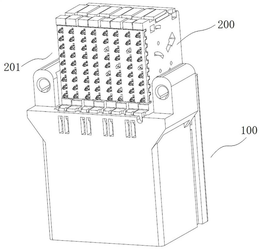
[0085] Such as Figure 1 to Figure 14 As shown, in this embodiment, the orthogonal connector is taken as an example to illustrate the related structure of the connector. The mating connector is mounted on the second circuit board when in use, and the first circuit board and the second circuit board are arranged orthogonally. The orthogonal connector includes a housing 100 in which multiple (at least two) wafers 200 are arranged. There are signal terminals 204 and grounding terminals 205 in the housing 100. The signal terminals 204 and grounding terminals 205 are installed at one end when in use. On the first circuit board, the other end is used to insert the signal terminal and the ground terminal in the matching connector.

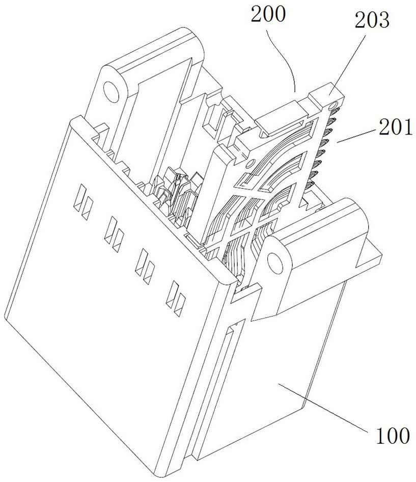
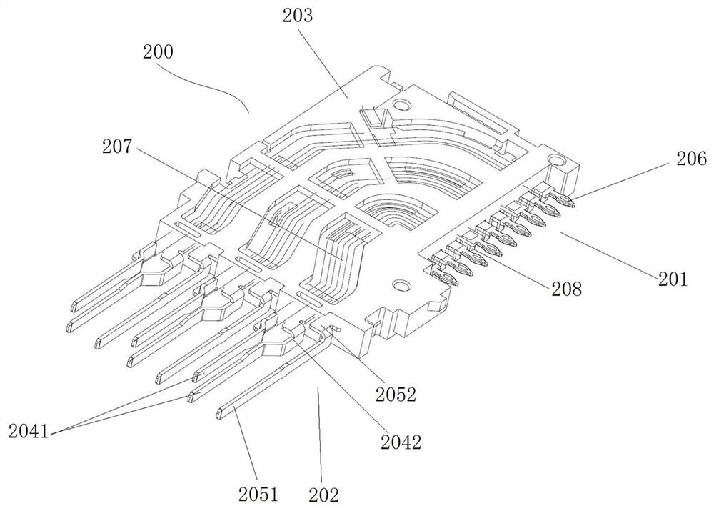
[0086] The structure of wafer 200 is as image 3 and Figure 4 As shown, the chip 200 includes an insulating frame 203 on which three signal differential pairs and three ground terminals 205 are fixed. The signal differential pairs and the ground termi...

Embodiment 1

[0108] In Embodiment 1, the grounding column is a rectangular column. In this embodiment, the shape of the grounding post may be cylindrical or other shapes.

specific Embodiment 3

[0110] In Embodiment 1, the grounding post is inserted into the grounding contact socket, and the end surface of the grounding post is flush with the surface of the separator. In this embodiment, the end surface of the grounding post may be located inside the grounding contact socket in the partition. Alternatively, in other embodiments, the grounding post may not be inserted into the grounding contact socket, that is, the grounding contact socket is small, and the grounding post is located at one side of the grounding contact socket.


PUM


Abstract

The invention relates to the technical field of signal transmission, in particular to a connector which comprises a shell. A wafer is arranged on the shell, the wafer comprises an insulating frame provided with a signal differential pair and a grounding terminal, the direction in which the connector is used for being inserted into an adaptive connector is defined as a first direction, and one end in the connector, which is used for being inserted into the adaptive connector, is a front end; the shell extends in the first direction, and an inner cavity penetrating in the first direction is formed in the shell. One of the side wall of the shell and the insulating frame is provided with a bayonet, and the other one of the side wall of the shell and the insulating frame is provided with a clamping block; the bayonet is provided with a rear stopping inner wall, and after the clamping block enters the bayonet, the rear stopping inner wall is used for being matched with the clamping block in a stopping mode in the first direction so as to prevent the wafer from being disengaged from the shell backwards when the wafer is inserted into an adaptive connector in a butt joint mode. The wafer and the shell are assembled in a clamped mode through the bayonet and the clamping block, the assembling mode is simple, the bayonet is provided with the rear stop inner wall, the bayonet can be matched with the clamping block in a stop mode, and the clamping block is prevented from being disengaged from the bayonet backwards.

Description

technical field [0001] The invention relates to the technical field of signal transmission, in particular to a connector. Background technique [0002] Existing high-speed connectors generally include a shell and a chip installed in the shell. The chip includes an insulating frame and a signal differential pair and a ground terminal on the insulating frame. The signal differential pair includes two signal terminals, and the signal terminal and the ground terminal are both There is a mounting end and a mating end, the mounting end is used to install on the circuit board, the mating end is used to plug in with the adapter connector, the signal terminal and the grounding terminal include the mounting terminal located at the mounting end (specifically, it can be connected to the printed board crimp-jointed fisheye), the signal terminal includes a signal contact at the mating end, and the ground terminal includes a ground contact at the mating end. [0003] In order to install t...

Claims


Application Information

Patent Timeline
Patent Type & Authority Applications(China)
IPC IPC(8): H01R13/518H01R13/516
CPCH01R13/518H01R13/516
Inventor 鲁中原杨兆振林杨潘波程喜乐史有权
Owner CHINA AVIATION OPTICAL-ELECTRICAL TECH CO LTD
Why Eureka
Try Eureka