Backlight module and luminous source encapsulation structure thereof

A technology of backlight module and light source, which is applied in the field of backlight module and its light source package structure, which can solve the problems of affecting the heat dissipation efficiency, the surface is not tightly bonded, and the display block is red, so as to avoid the effect of overheating of the chip

Active Publication Date: 2011-01-12
TCL CHINA STAR OPTOELECTRONICS TECH CO LTD
View PDF3 Cites 10 Cited by
  • Summary
  • Abstract
  • Description
  • Claims
  • Application Information

AI Technical Summary

Problems solved by technology

However, the disadvantage of the LED packaging structure is that the temperature in the working process is extremely high. If the fixing plate of the backlight module cannot take away the heat energy generated by the LED packaging structure in time, it will not only cause the temperature near the LED packaging structure to rise significantly. If the temperature is too high, the temperature of each display area of ​​the LCD will be uneven, and the display area of ​​the LCD panel near the light-emitting diode packaging structure may also appear red due to excessive temperature, which will affect the imaging quality of the LCD.
Furthermore, the light-emitting diode itself is very easy to affect its luminous efficiency and working stability due to the temperature rise in the working process, so it may also reduce its service life due to long-term high temperature
In addition, if the LED packaging structure is simply glued on the fixing board with an adhesive or screwed on the fixing board, since the LED packaging structure and the fixing board are not in direct thermal contact, or the two There is an insulating adhesive between the two or the surfaces between the two are not tightly bonded, so the heat dissipation efficiency will be affected to a certain extent
In addition, under long-term high temperature conditions, the adhesive may also deteriorate and lose its viscosity, causing the LED packaging structure to separate from the fixing plate. If the heat energy of the LED packaging structure cannot be taken away by the fixing plate in real time, the LED packaging structure will be damaged. There is a potential risk of overheating and burning
[0005] Therefore, it is indeed necessary to provide a light-emitting source packaging structure for the light-emitting diodes of the backlight module to solve the heat dissipation problem existing in the prior art.

Method used


Image

  • Backlight module and luminous source encapsulation structure thereof
  • Backlight module and luminous source encapsulation structure thereof
  • Backlight module and luminous source encapsulation structure thereof

Examples


Embodiment Construction

[0026] In order to make the above objects, features and advantages of the present invention more comprehensible, preferred embodiments of the present invention are exemplified below and described in detail in conjunction with the accompanying drawings. Furthermore, the directional terms mentioned in the present invention, such as "up", "down", "front", "back", "left", "right", "inside", "outside", "side", etc., It is only for orientation with reference to the attached drawings. Therefore, the directional terms used are used to illustrate and understand the present invention, but not to limit the present invention.

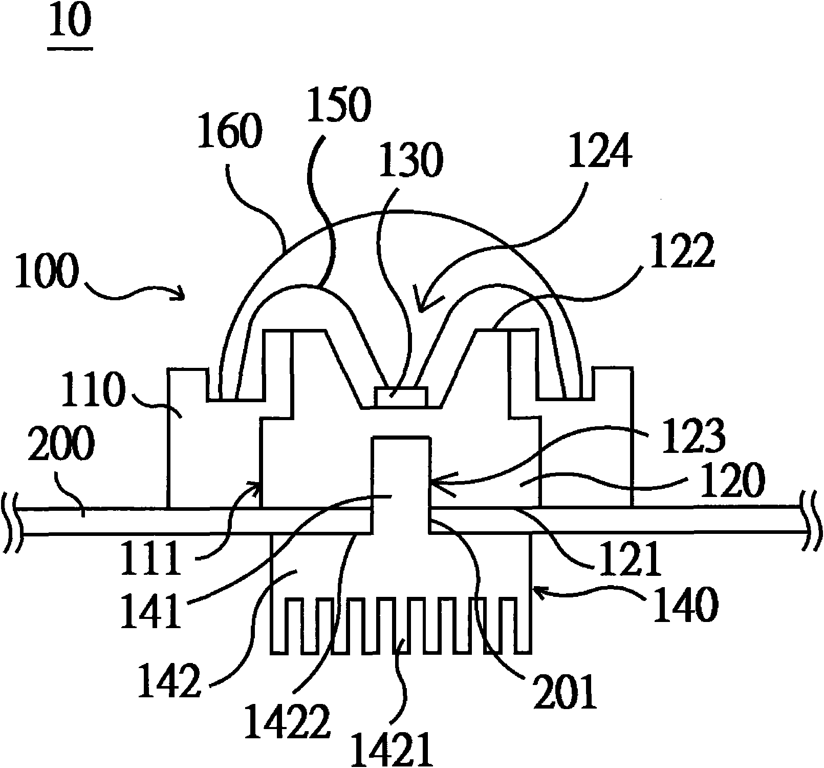
[0027] Please refer to figure 1 As shown, it discloses a schematic diagram of the light source packaging structure of the backlight module of the first preferred embodiment of the present invention, wherein the backlight module 10 of the first preferred embodiment of the present invention is mainly used in the field of liquid crystal displays (LCD), and the backli...


PUM


Abstract

The invention discloses a backlight module and a luminous source encapsulation structure thereof. The luminous source encapsulation structure comprises a heat radiating seat, at least one chip and a heat radiating and fixing piece, wherein the heat radiating seat is provided with a combining hole, the dimension of the heat radiating and fixing piece is less than that of the heat radiating seat, and the heat radiating and fixing piece comprises a combining post and a heat radiating fin with a butt surface; the combining post passes through a through hole of a fixing plate and is combined with the combining hole, the butt surface of the heat radiating fin is supported on the fixing plate, therefore, the heat radiating seat and the heat radiating and fixing piece can be stably combined on both sides of the fixing plate in order to ensure the tight binding relation with the fixing plate and increase assembling reliability, meanwhile, the heat radiating fin can be used for increasing the heat radiating effect of the heat radiating seat in extra, and therefore, the heat radiating fin can assuredly help the chip to reduce temperature in order to avoid the work efficiency reduction of the chip and is beneficial to ensuring that the chip stably operates and prolonging the service life.

Description

【Technical field】 [0001] The present invention relates to a backlight module and its packaging structure for light emitting sources, in particular to a light emitting source that utilizes heat dissipation fixtures to securely combine the packaging structure of light emitting sources on a fixing plate and uses heat dissipation fins to dissipate heat. Packaging structure and a backlight module with the light emitting source packaging structure. 【Background technique】 [0002] Liquid crystal display (liquid crystal display, LCD) is a flat panel display device (flat panel display, FPD) that uses the characteristics of liquid crystal materials to display images. Power consumption and other advantages have become mainstream products in the entire consumer market. However, the liquid crystal material of the liquid crystal display cannot emit light by itself, and an external light source must be provided. Therefore, a backlight module is additionally provided in the liquid crystal ...

Claims


Application Information

Patent Timeline
Patent Type & Authority Applications(China)
IPC IPC(8): F21S8/00F21V17/12F21V17/16F21V29/00H01L33/48H01L33/64
CPCG02F1/133603H01L33/642G02F2001/133628F21V29/004H01L33/62H01L2224/48091F21Y2101/02F21Y2115/10G02F1/133628H01L2924/00014F21V29/763
Inventor 周革革
Owner TCL CHINA STAR OPTOELECTRONICS TECH CO LTD
Why Eureka
Try Eureka