Bearing positioning structure for motor

a technology for positioning structures and bearings, applied in the direction of bearing unit rigid support, record information storage, instruments, etc., can solve problems such as unreliable bearing positioning, and achieve the effect of improving assembly reliability

Active Publication Date: 2009-10-22
SUNONWEALTH ELECTRIC MACHINE IND
View PDF11 Cites 10 Cited by
  • Summary
  • Abstract
  • Description
  • Claims
  • Application Information

AI Technical Summary

Benefits of technology

[0009]An object of the present invention is to provide a bearing positioning structure for a motor with improved assembling reliability.
[0010]Another object of the present invention is to provide a bearing positioning structure for promoting the assembling reliability and prolonging the life of the motor.
[0011]A further object of the present invention is to provide a bearing positioning structure for a motor with improved effect in preventing entrance of dusts into the motor, thereby prolonging the life of the motor.SUMMARY OF THE INVENTION
[0026]Preferably, the stator further includes a second coupling section, and the axial tube includes an engaging portion for engaging with the second coupling section of the stator, thereby securely mounting the stator to the axial tube.

Problems solved by technology

However, the above conventional bearing positioning structure for a motor has some drawbacks.
First, the axial tube 111 easily deforms after a period of time due to heat expansion and cold shrinkage as well as stress generated during operation of the motor such that the supporting member 13 and the positioning member 15 cannot be fixed in the axial tube 111, leading to unreliable positioning of the bearing 14.

Method used


Image

  • Bearing positioning structure for motor
  • Bearing positioning structure for motor
  • Bearing positioning structure for motor

Examples


first embodiment

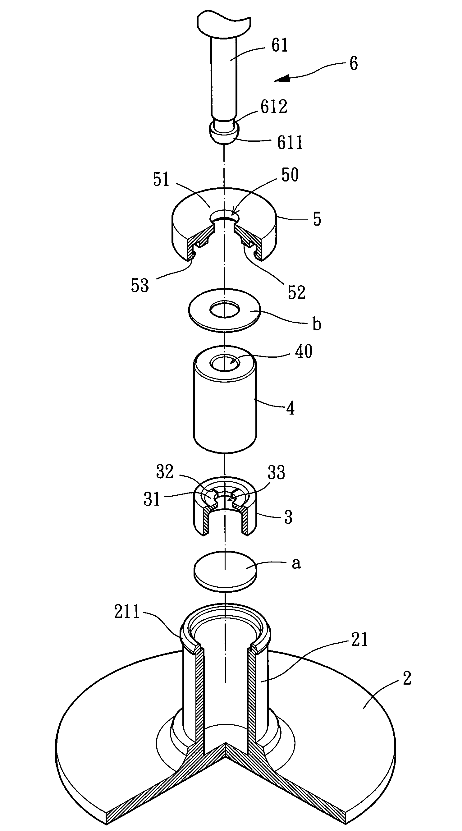
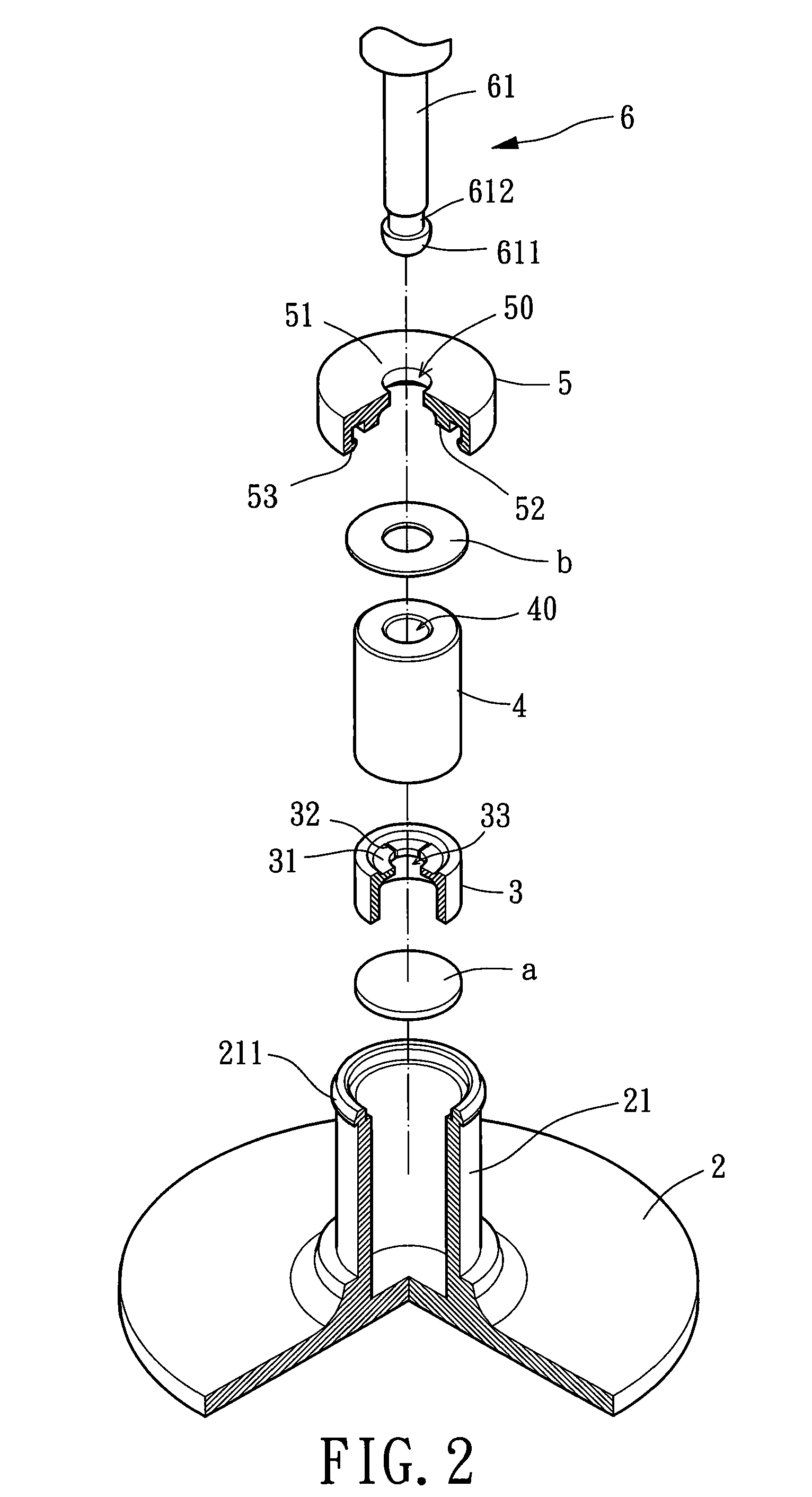
[0035]Referring to FIGS. 2 and 3, a bearing positioning structure in accordance with the present invention comprises a base 2, a restraining member 3, a bearing 4, a positioning member 5, and a rotor 6. Mounted to the base 2 is an axial tube 21 and a stator 22, wherein the axial tube 21 may be assembled to or integrally formed with the base 2 for receiving motor elements including the restraining member 3, the bearing 4, and the positioning member 5. The stator 22 may be of radial winding type or axial winding type. The restraining member 3 restrains axial movement of a shaft 61 of the rotor 6 relative to the axial tube 21. The bearing 4 may be an oily bearing, a ball bearing, a fluid dynamic bearing, etc. The shaft 61 is rotatably extended through the bearing 4. The positioning member 5 is engaged with the axial tube 21 for reliably positioning the bearing 4 in the axial tube 21.

[0036]Still referring to FIGS. 2 and 3, the axial tube 21 of the first embodiment in accordance with the...

third embodiment

[0044]Still referring to FIGS. 5 and 6, the stator 22 of the third embodiment is engaged with the axial tube 21 by providing a second coupling section 222 on a bottom portion of the stator 22 for engaging with an engaging portion 212 of the axial tube 21. Hence, the stator 22 is reliably fixed to the axial tube 21. Preferably, the engaging portion 212 is formed on an outer circumference of the axial tube 21 and corresponding to the second coupling section 222. Preferably, the first and second coupling sections 221 and 222 are hooks.

[0045]Still referring to FIGS. 5 and 6, in assembly of the motor elements of the third embodiment, the restraining member 3, the bearing 4, and the positioning member 5 are mounted into the axial tube 21 in sequence. Next, the first coupling section 221 and the second coupling section 222 of the stator 22 are respectively engaged with the coupling portion 53 of the positioning member 5 and the engaging portion 212 of the axial tube 21 such that the stator...


PUM


Abstract

A bearing positioning structure for a motor includes an axial tube and a positioning member. The positioning member includes a pressing portion and a coupling portion. The coupling portion of the positioning member is engaged with a coupling section of the axial tube for securely mounting the positioning member to the axial tube, with the pressing portion of the positioning member pressing against a bearing to position the bearing in the axial tube. In another example, the coupling portion of the positioning member engages with a coupling section on a stator.

Description

[0001]This application is a Divisional of co-pending application Ser. No. 11 / 590,807, filed on Nov. 1, 2006, and for which priority is claimed under 35 U.S.C. § 120; the entire contents of which are hereby incorporated by reference.BACKGROUND OF THE INVENTION[0002]1. Field of the Invention[0003]The present invention relates to a positioning structure for a motor and, more particularly, to a bearing positioning structure for a motor with a positioning member providing with a coupling portion and a pressing portion for stably positioning at least one motor component in an axial tube of a base.[0004]2. Description of Related Art[0005]FIG. 1 of the drawings illustrates a conventional bearing positioning structure for a motor 1 comprising a base 11, a stator 12, a supporting member 13, a bearing 14, a positioning member 15, and a rotor 16. The base 11 includes an axial tube 111 for receiving the bearing 14. The stator 12 includes a winding 121. The supporting member 13 is fixed in an end...

Claims


Application Information

Patent Timeline
Patent Type & Authority Applications(United States)
IPC IPC(8): H02K5/167
CPCF16C35/02G11B19/2018F16C2370/12H02K5/163G11B19/2036
Inventor HORNG, ALEXLU, YU-YUANSHAN, DUO-NIEN
Owner SUNONWEALTH ELECTRIC MACHINE IND
Why Eureka
Try Eureka