Sync signal mapping method and device for relay link

A technology of synchronization signal and mapping method, which is applied in the direction of synchronization device, pilot signal distribution, multiplexing communication, etc., and can solve the problem of out-of-synchronization between the sending and receiving parties

Inactive Publication Date: 2014-12-10
海宁市盐官工业投资有限公司
View PDF4 Cites 0 Cited by
  • Summary
  • Abstract
  • Description
  • Claims
  • Application Information

AI Technical Summary

Problems solved by technology

Considering the clock accuracy of both transceivers, there will be sampling deviation between the transceiver and the transceiver, which will cause the synchronization of both parties. If the RN works according to the eNode-B clock precision, the RN needs to perform synchronous tracking every 300ms; if the RN works according to the UE clock precision work, approximately every 5ms, RN needs to perform synchronous tracking

Method used


Image

  • Sync signal mapping method and device for relay link
  • Sync signal mapping method and device for relay link
  • Sync signal mapping method and device for relay link

Examples


Embodiment Construction

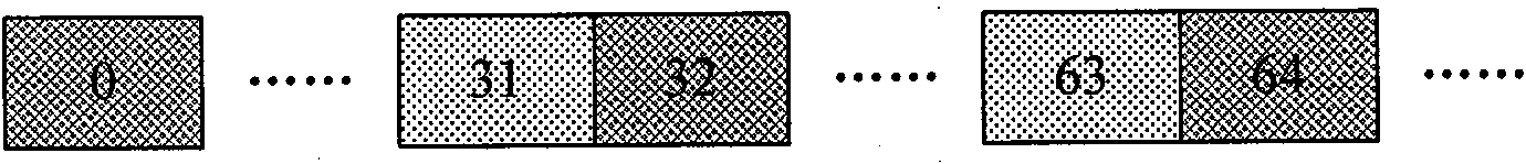
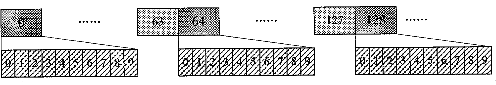
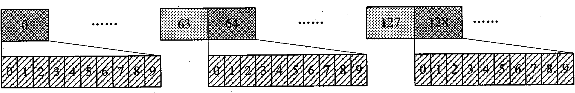
[0079] Figure 4 It is a flow chart of the synchronization signal mapping method of the relay link of the present invention, such as Figure 4 shown, including the following steps:

[0080] Step 400: Generate a synchronization sequence of the backhaul link between the base station and the relay node.

[0081] In this step, the method for generating the synchronization sequence for the link from the base station to the relay node is the same as or different from the method for generating the primary synchronization sequence for the link between the base station and the terminal. Specifically:

[0082] When the synchronization sequence generation method of the link from the base station to the relay node is the same as the generation method of the main synchronization sequence of the link from the base station to the terminal, the specific implementation is: the synchronization signal is composed of a frequency domain Zadoff-Chu sequence, and the root sequence of the Zadoff-Ch...


PUM


Abstract

Provided are a method and an apparatus for mapping a synchronization signal on a relay link in the present invention. By generating a synchronization sequence, and by determining the mapping positions, in the frequency direction and the time direction, of the synchronization signal, the mapping mode of the synchronization signal on a backhaul link between a Base Station(BS) and a Relay Node(RN) is implemented. The method in the present invention can be well adapted to a backhaul link between a BS and a RN and the mapping mode of the synchronization signal is simple, thus not only guaranteeing backward compatibility(compatible with a Long Term Evolution(LTE) system), but also solving the problem how the RN can correctly receive a Primary Synchronization Signal(PSS) and a Secondary Synchronization Signal(SSS) transmitted by the BS, only with a need of low cost, while guaranteeing that the RN can normally finish the tracking work.

Description

technical field [0001] The invention relates to a synchronous signal mapping technology, in particular to a synchronous signal mapping method and device for a relay link. Background technique [0002] The Long Term Evolution (LTE, Long Term Evolution) system, the Long Term Evolution Advanced (LTE-A, Long Term Evolution Advanced) system, and the advanced International Mobile Telecommunications system (IMT-Advanced, International Mobile Telecommunication Advanced) all use orthogonal frequency A system based on Orthogonal Frequency Division Multiplexing (OFDM, Orthogonal Frequency Division Multiplexing) technology, in the OFDM system is mainly a time-frequency two-dimensional data form. figure 1 is a schematic diagram of the relationship between resource blocks and subcarriers, such as figure 1 As shown in , all the small squares represent a resource block, and the slash hatches represent subcarriers. [0003] In the LTE system and LTE-A system, a resource block (RB, Resource...

Claims


Application Information

Patent Timeline
Patent Type & Authority Patents(China)
IPC IPC(8): H04B7/26H04B7/14H04W56/00
CPCH04B7/2606H04W56/0085H04J11/0073H04J11/0076H04L5/0048
Inventor 毕峰梁枫杨瑾袁明吴栓栓袁弋非
Owner 海宁市盐官工业投资有限公司
Why Eureka
Try Eureka