Bobbin holder

A bobbin rack and bobbin technology, applied in the field of bobbin racks, can solve problems such as short running time of the bobbin racks

Inactive Publication Date: 2011-01-26
OERLIKON TEXTILE GMBH & CO KG
View PDF1 Cites 7 Cited by
  • Summary
  • Abstract
  • Description
  • Claims
  • Application Information

AI Technical Summary

Problems solved by technology

The resulting fatigue phenomena of the material therefore allow only a short operating time of the bobbin holder

Method used


Image

  • Bobbin holder
  • Bobbin holder
  • Bobbin holder

Examples


Embodiment Construction

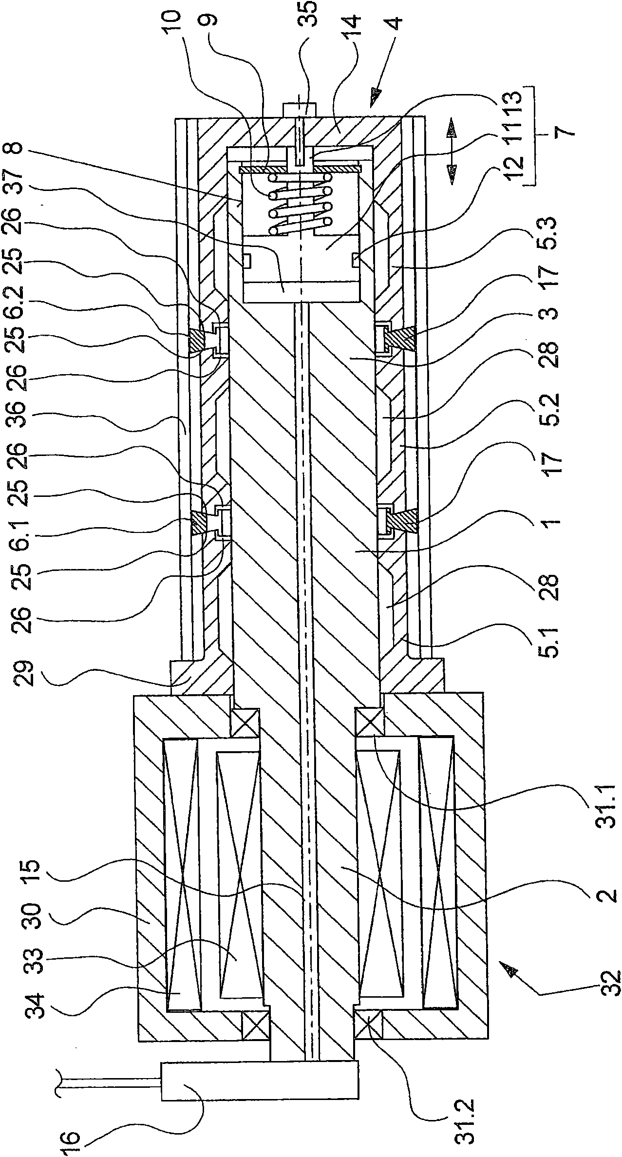
[0025] exist figure 1 A first embodiment of the bobbin holder according to the invention is schematically shown in sectional view in FIG. The bobbin holder has a drive shaft 1 with a bearing end 2 and an overhanging tensioning end 3 . Tensioning means 4 are held on the overhanging tensioning end 3 of the drive shaft 1 in order to tension a bobbin 36 on the circumference of the tensioning end 3 of the drive shaft 1 .

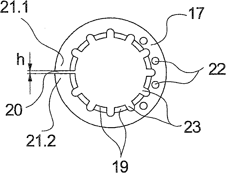
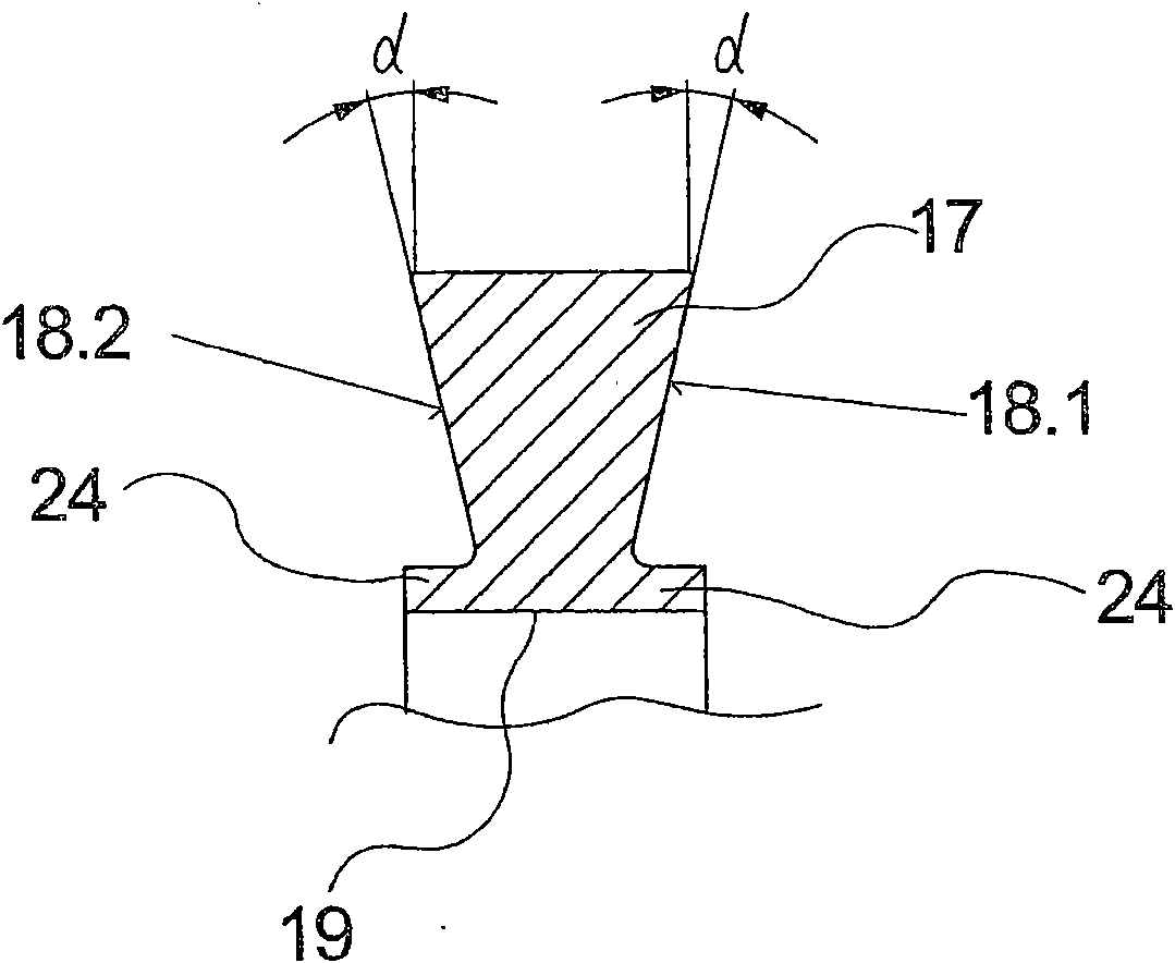
[0026] The tensioning mechanism 4 has a plurality of clamping sleeves 5.1, 5.2 and 5.3 arranged successively on the circumference of the drive shaft 1. Between the clamping sleeves 5.1 and 5.2 and between the clamping sleeves 5.2 and 5.3 are respectively arranged tensioning rings 6.1 and 6.2. The tensioning rings 6.1 and 6.2 protrude with tensioning flanges 17 between the clamping sleeves 5.1, 5.2 and 5.3.

[0027] To illustrate tensioning rings 6.1 and 6.2, first refer to figure 2 with 3 , one of the tensioning rings 6.1 is schematically shown in several v...


PUM


Abstract

The invention relates to a bobbin holder for tensioning a bobbin tube (36) and receiving a wound thread bobbin. The bobbin holder comprises a rotatable drive shaft (1) that is connected to a drive (32) with a bearing end thereof and that has a tensioning device (4) for tensioning a bobbin tube on a tensioning end. The tensioning device (4) comprises a plurality of bobbin tubes (5.2, 5.3) on the periphery of the drive shaft (1) and interposed tensioning rings (6.1). A tensioning piston (7) guided on the free end (2) of the drive shaft acts upon at least one of the bobbin tubes to deform the tensioning rings. In order to allow the use of high fatigue strength materials for the tensioning ring, the tensioning ring comprises a continuous separating slot (20) on the periphery, which extends between two opposite ring ends (21.1, 21.2) of the tensioning ring, deformation being essentially achieved by an expansion of the tensioning ring.

Description

technical field [0001] The invention relates to a bobbin holder for tensioning bobbins and receiving wound filament bobbins. Background technique [0002] A bobbin holder of this type is known from US Pat. No. 4,458,850. [0003] For winding the filaments, the wound filament spool is usually wound and held on the periphery of a bobbin. The bobbins are held and driven by a bobbin holder which has a detachable tensioning mechanism so that the bobbins can be easily replaced at the beginning of the process and at the end of the process. Here, in particular bobbin holders have proven to be advantageous, in which the bobbin tubes are placed over the overhanging free ends of the bobbin holders. In such bobbin holders, the tensioning means for securing the bobbins are arranged on the circumference of the drive shaft. [0004] Such a bobbin holder is known from US Pat. No. 4,458,850. The tensioning mechanism formed on the circumference of a drive shaft consists of a plurality of ...

Claims


Application Information

Patent Timeline
Patent Type & Authority Applications(China)
IPC IPC(8): B65H54/54B65H75/24
CPCB65H75/245B65H2701/31B65H54/543
Inventor J·维斯特法尔C·马蒂斯F·莱内曼
Owner OERLIKON TEXTILE GMBH & CO KG
Why Eureka
Try Eureka