Slide fastener opener

A technology for parts and zippers, applied in the field of opening parts for zippers, can solve the problem that the opening part 60 is not perfect, etc.

Active Publication Date: 2011-02-23
YKK CORP
View PDF2 Cites 5 Cited by
  • Summary
  • Abstract
  • Description
  • Claims
  • Application Information

AI Technical Summary

Problems solved by technology

[0021] However, the opening member 60 of the third example is not perfect
After the slider is inserted into the holding part 61 and abutted against and fixed on the pivot insertion part 64, the tooth chain 67 to be engaged is inserted from the shoulder of the slider or between the inner and outer flanges, and then the slider is slid in the direction of engagement. During the op...

Method used


Image

  • Slide fastener opener
  • Slide fastener opener
  • Slide fastener opener

Examples


Embodiment 1

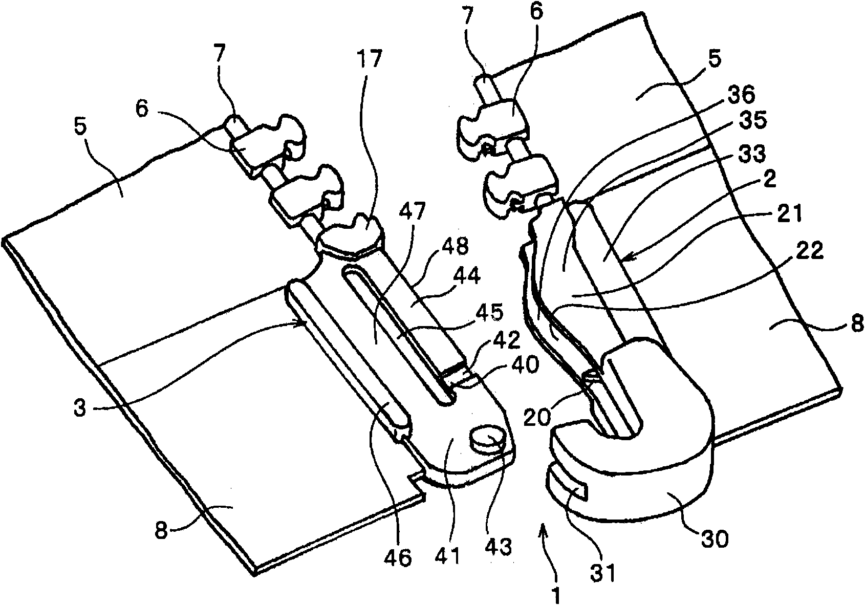
[0127] Such as figure 1 as shown, Figure 1~6 The slide fastener opening member 1 of the shown embodiment 1 is formed by two parts of the pivot body 2 and the insertion body 3, and when the pivot body 2 and the insertion body 3 are arranged on the fastener tape 5, a pair of left and right The opposite side edges of the fastener tape 5 are woven or braided with the core wire 7, and the core wire 7 is continuously injection-molded using a resin such as polyoxymethylene or polyamide to form the fastener element 6. The continuous element 6 is removed at a certain interval to form a space portion, and after the reinforcement tape 8 is pasted on the fastener tape 5 in the form of surrounding the core wire 7 at the space portion, the same material as that of the element 6 is used for the space portion. Made of resin, the pivot body 2 and the insert body 3 are integrally formed on the core wire 7 by an injection molding mechanism in such a way as to be connected with the fastener el...

Embodiment 2

[0138] Figure 7-9 In the illustrated embodiment 2, the engaged portion 40 is formed on the surface of the edge portion 44 of the insert plate 41 on the insert body 3, and the side of the engaged portion 40 on which the pivot 43 protrudes is provided. The chain element 6 is formed higher, that is, thicker, and the chain element 6 is formed lower, that is, thinner, so that a step portion 50 is provided, and the side of the chain element 6 of the step portion 50 is used as a concave portion 42, and the surface of the groove 22 on the pivot body 2 A stepped portion 34 capable of engaging with the stepped portion 50 is provided on the inner surface 23 . The stepped portion 34 forms a larger gap on the side of the pivot portion 30 and a smaller gap on the side of the element 6 , and is provided with an engaging portion 20 corresponding to the stepped portion 50 formed on the edge portion 44 .

[0139] By sliding the slider 10 in the direction to close the fastener chain 9 on eithe...

Embodiment 3

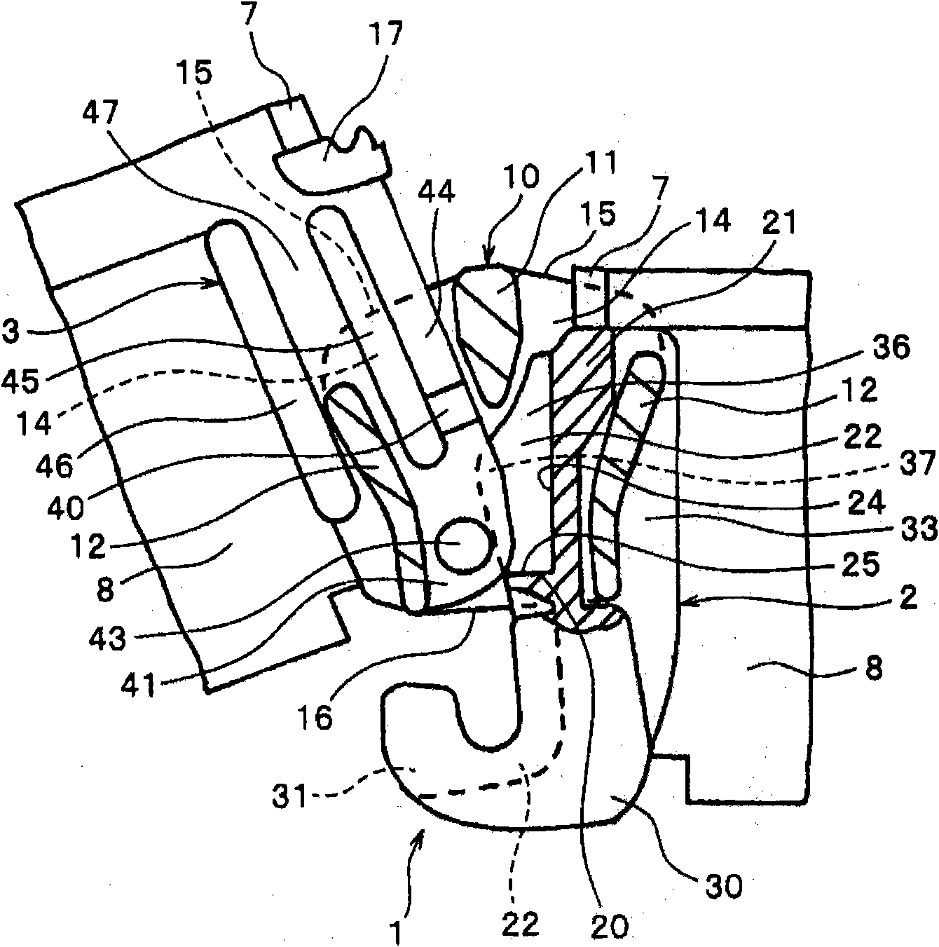
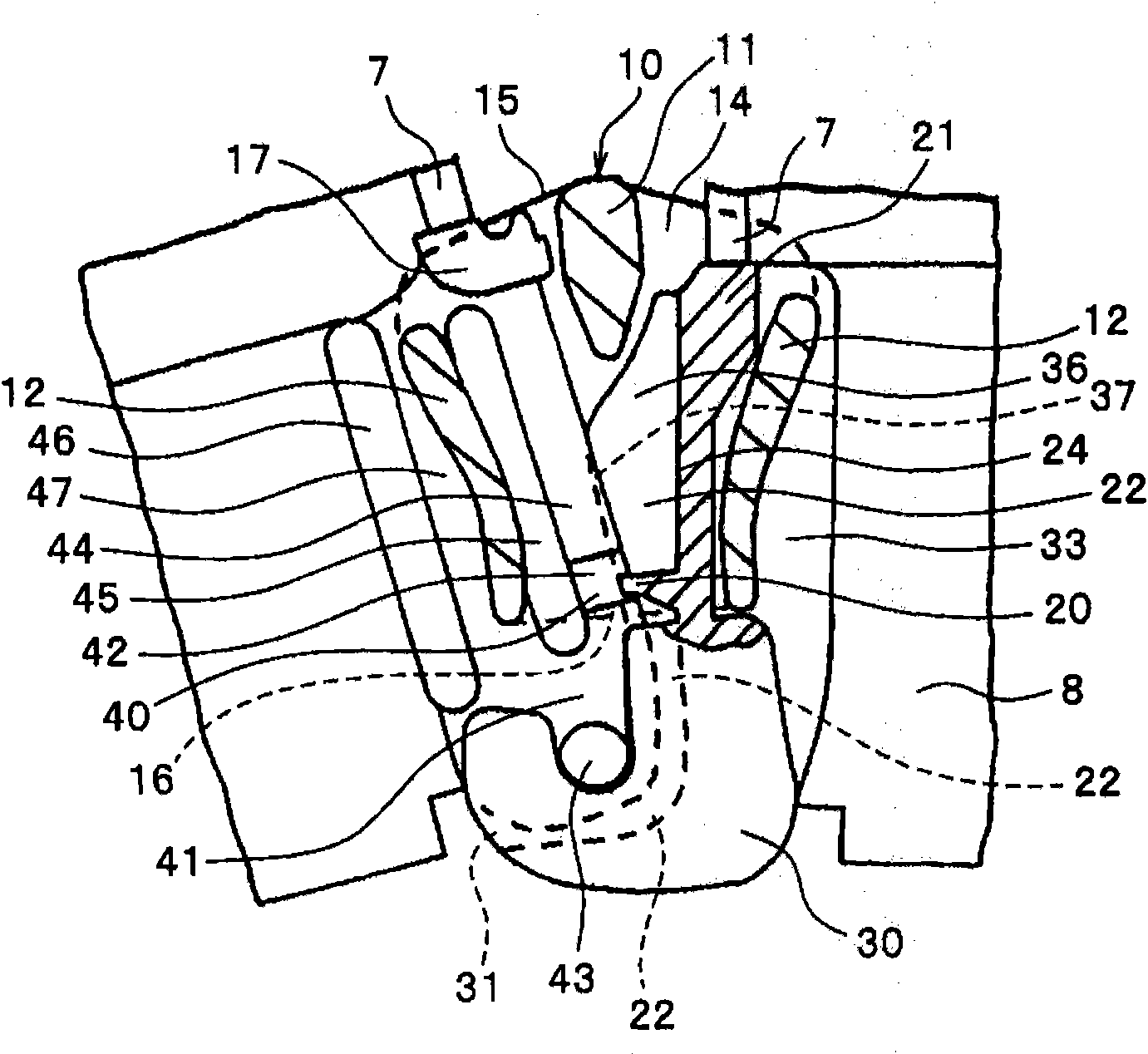
[0143] Figure 10 , 11 In the illustrated third embodiment, the forms of the engaging portion 20 and the engaged portion 40 are different from those of the foregoing embodiments. That is, in the foregoing embodiments, the engaging portion 20 and the engaged portion 40 are formed on the inner and outer surfaces of the pivot body 2 and the insertion body 3, but in this embodiment, the engaging portion 20 and the engaged portion 40 Formed on the sides, ie, the bottom 24 of the groove 22 on the holding portion 21 , and the side end 48 of the edge portion 44 of the insertion plate 41 . The pivot body 2 and the insertion body 3 are arranged on abutting surfaces with side faces.

[0144] In the bottom 24 of the groove 22 on the holding portion 21 of the pivot body 2 , a protruding portion 29 protruding in an arc shape is provided at a position close to the pivot portion 30 to form the engaging portion 20 . The convex part 29 does not necessarily have to be arc-shaped, and may be a s...


PUM


Abstract

A slide fastener opener for preventing an insert from sliding together with a slider starting to move even if the insert inserted into the opener is not held or the slider is operated by a single hand. The opener is equipped with a pivot (2) for holding the slider at an end of one of fastener stringers (9) attached and the slider and the insert (3) to be inserted into the pivot (2) attached at an end of the other stringer (9). The pivot (2) is equipped with a holding part (21) formed of a recessed groove (22) and a J-shaped pivot (30) capable of fitting a pivot shaft (43) provided on the insert (3) at its end, an engaging part (20) protruding into the recessed groove (22), and a dent (42) on a side rim of an insert plate (41) of the insert (3) to form an engaged part (40). The opener is formed to prevent the engaging part (20) and the engaged part (40) from engaging and sliding together with the slider starting to move.

Description

technical field [0001] The opening part in the zipper of the present invention is formed by two parts, the pivot body and the insertion body, and the pivot body is installed at the end of the tooth chain on one side, and the slider inserted on the tooth chain is slid and abutted against it. After the pivot body is installed, insert the insert installed on the end of the tooth chain on the other side from the shoulder of the slider or between the inner and outer flanges on the side, so that the pivot body and the insert body are hooked and combined , slide the slider in the locking direction to lock the left and right tooth chains. Moreover, this invention relates to the opening member of the slide fastener which can isolate|separate the fastener chain on either side by performing reverse operation. Background technique [0002] In the past, the following opening parts are generally known: the opening part called the plug-in-separation part is formed by these three parts of ...

Claims


Application Information

Patent Timeline
IPC IPC(8): A44B19/38
CPCA44B19/38
Inventor 濑川清正
Owner YKK CORP
Why Eureka
Try Eureka