
Electric nail hammer

A nail hammer and electric technology, applied in nail tools, nail dispensers, packaging, etc., can solve the problems of easy hitting fingers, low work efficiency, low safety, etc., to increase convenience and universality, and save manpower , the effect of improving efficiency

Inactive Publication Date: 2011-03-30
苏州卓识商务咨询有限公司
View PDF5 Cites 0 Cited by
  • Summary
  • Abstract
  • Description
  • Claims
  • Application Information

AI Technical Summary

Problems solved by technology

First of all, driving a nail with a hammer requires a lot of force to drive the nail in, and the labor intensity is high.
Secondly, nailing with a nail hammer requires fingers to hold the middle of the nail. During the hitting process, once there is a deviation, it is easy to hit the finger, causing injury accidents, and its safety is low.
Finally, even for professional carpenters, if a large number of nails need to be nailed every day, even skilled workers can hardly nail more than 20 nails per minute by hand under the premise of ensuring accuracy. nails, work efficiency is also low
Therefore, in the prior art, also there is not a kind of power tool that can realize the process of finishing nails in an automatic manner.

Method used


Image

  • Electric nail hammer
  • Electric nail hammer

Examples


Embodiment Construction

[0021] The preferred embodiments of the present invention are described in detail below, so that the advantages and features of the present invention can be more easily understood by those skilled in the art, so as to define the protection scope of the present invention more clearly.

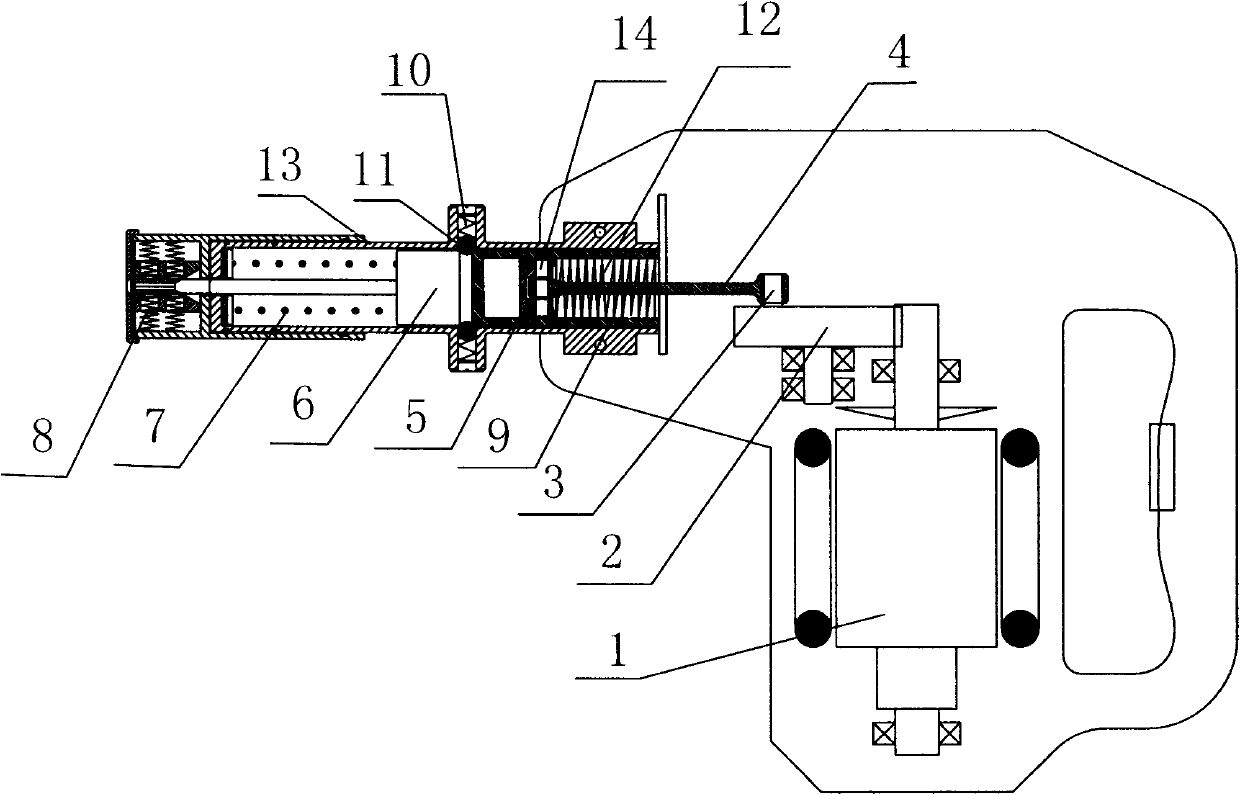
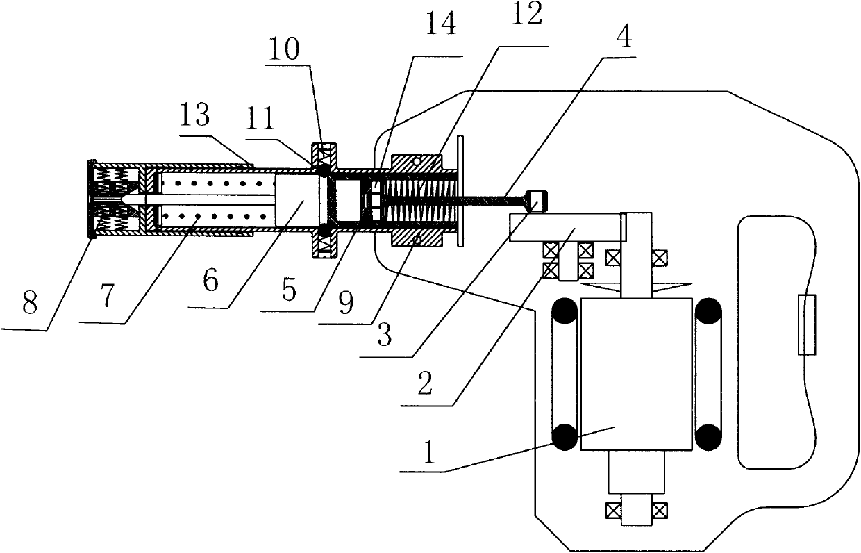
[0022] See attached figure 1 , an electric mace comprising

[0023] It includes a driving device for generating driving force. In this embodiment, the driving device is a motor 1 .

[0024] Transmission device, one end of the connecting rod 4 of the transmission device is rotatably connected with the drive pin 3 arranged on the end face of the driven gear 2 of the gear set and perpendicular to its end face; the other end is rotatably connected with the piston 5 through the piston pin 14 .

[0025] The guide sleeve device 13 is a hollow cylinder used to limit the movement path of the rear spring type pneumatic energy storage device.

[0026] The rear spring type pneumatic energy storage device ...


PUM


Abstract

The invention discloses an electric nail hammer, which comprises a driving device, a transmission device, a guide sleeve device (13), and a rear spring type pneumatic energy storage device, wherein the driving device is used for generating driving force; the transmission device comprises a gear set and a connecting rod mechanism connected with the driving device; the guide sleeve device (13) is used for limiting the motion path of the rear spring type pneumatic energy storage device; the rear spring type pneumatic energy storage device comprises a cylinder (9) arranged in the guide sleeve device (13), a piston (5) arranged in the cylinder (9), and a triggering device which is arranged in the guide sleeve device (13) and is used for blocking or releasing the cylinder (9); the piston (5) separates the cylinder (9) into a first cavity and a second cavity, and passes through the second cavity to connect with a transmission mechanism; and a spring (12) stretching along the axial direction of the cylinder (9) is arranged in the second cavity. The invention overcomes the defects of the prior art, and provides a high-efficiency electric nail hammer which can automatically finish nail striking.

Description

technical field [0001] The invention relates to an automatic installation device for nails, in particular to an automatic installation device for round nails. Background technique [0002] At present, nail hammers on the market rely on manual hammering to complete the nailing process. During the operation, the operator swings the nail hammer to hit the bottom of the nail, so that the nail is embedded in the object to be fixed. This method is used There are limitations. First of all, it takes a lot of force to nail the nails through a hammer, and the labor intensity is high. Secondly, nails need to be held by fingers to hold the middle of the nail by hammering. During the hitting process, once there is a deviation, it is easy to hit the fingers, causing injury accidents, and its safety is low. Finally, even for professional carpenters, if a large number of nails need to be nailed every day, even skilled workers, under the premise of ensuring accuracy, it is difficult to nai...

Claims


Application Information

Patent Timeline
Patent Type & Authority Applications(China)
IPC IPC(8): B25C1/04B25C3/00
Inventor 温庆普
Owner 苏州卓识商务咨询有限公司
Learn More