Method and device for rendering concave polygon

A technology of concave polygons and polygons, applied in the field of graphics processing, can solve problems such as high cost

Inactive Publication Date: 2013-03-20
FUJITSU LTD
View PDF0 Cites 0 Cited by
  • Summary
  • Abstract
  • Description
  • Claims
  • Application Information

AI Technical Summary

Problems solved by technology

However, this method is expensive in accessing memory to determine whether a pixel is inside a concave polygon, and is only suitable for monochrome shading

Method used


Image

  • Method and device for rendering concave polygon
  • Method and device for rendering concave polygon
  • Method and device for rendering concave polygon

Examples


Embodiment Construction

[0034] Features and exemplary embodiments of various aspects of the invention will be described in detail below. The description of the following embodiments covers numerous specific details in order to provide a thorough understanding of the invention. It will be apparent, however, to one skilled in the art that the present invention may be practiced without some of these specific details. The following description of the embodiments is only to provide a clearer understanding of the present invention by showing examples of the present invention. The present invention is by no means limited to any specific configuration and algorithm presented below, but covers any modification, replacement and improvement of related elements, components and algorithms without departing from the spirit of the present invention.

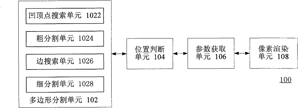
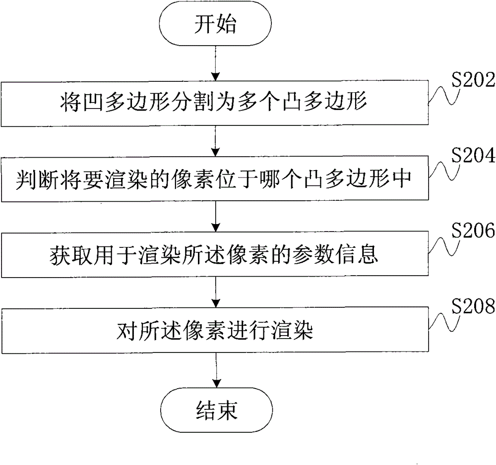
[0035] figure 1 and figure 2 A logical block diagram and a flow chart of an apparatus and method for rendering concave polygons according to an embodiment of the ...


PUM


Abstract

The invention discloses a method and device for rendering a concave polygon. The method for rendering the concave polygon comprises the following steps of: segmenting the concave polygon into a plurality of convex polygons; judging that pixels to be rendered are positioned whose convex polygons; acquiring parameter information for rendering the pixels by using coordinate information of the pixels and coordinate information and parameter information of each apex of the convex polygon on which the pixels are positioned; and rendering the pixels by using the parameter information.

Description

technical field [0001] The present invention relates to the field of graphics processing, and more particularly to a method and device for rendering concave polygons. Background technique [0002] Efficiently rendering concave polygons is very difficult in computer graphics. Since a concave polygon has no specific shape and the number of vertices is at least 4 and at most infinite, it is not easy to judge whether a pixel is in a concave polygon. Also, it is difficult to render concave polygons using methods such as Gouraud shading or Phong shading. [0003] A common approach to shading is to first decompose a concave polygon into a series of triangles, and then render each triangle incrementally. So far, there is no way to triangulate a concave polygon in linear time complexity, so this process is very time-consuming. [0004] Another common shader method is to fill concave polygons in scanline order. Specifically, a parity test is first used to determine whether a pixel...

Claims


Application Information

Patent Timeline
Patent Type & Authority Patents(China)
IPC IPC(8): G06T11/20
Inventor 谭志明白向晖洲镰康付轩
Owner FUJITSU LTD
Why Eureka
Try Eureka