Check patentability & draft patents in minutes with Patsnap Eureka AI!

A detection device and method for Ethernet partial protection

A local protection and detection device technology, applied in the field of network communication, can solve the problems of many nodes involved, long protection switching time, etc., and achieve the effect of improving efficiency

Active Publication Date: 2015-08-12
ZTE CORP
View PDF4 Cites 0 Cited by
  • Summary
  • Abstract
  • Description
  • Claims
  • Application Information

AI Technical Summary

Problems solved by technology

[0008] Although the end-to-end protection technology of PBB-TE can effectively protect the tunnel, this end-to-end protection scheme not only takes a long time for protection switching, but also involves too many nodes

Method used


Image

  • A detection device and method for Ethernet partial protection
  • A detection device and method for Ethernet partial protection
  • A detection device and method for Ethernet partial protection

Examples


Embodiment Construction
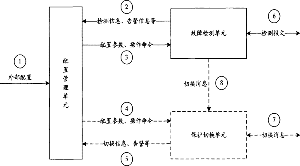
[0039] The basic idea of ​​the present invention is: the configuration management unit in the device is used to receive external configuration commands or parameters, and send the operation commands or configuration parameters applied to fault detection to the fault detection unit; Receive operation commands or configuration parameters, run fault detection according to the operation commands or configuration parameters, and perform fault detection on segments in the local protection domain; feedback detection information or alarm information to the configuration management unit.

[0040] The implementation of the technical solution will be further described in detail below in conjunction with the accompanying drawings.

[0041] Such as figure 2 As shown, a detection device for local protection of Ethernet is located on any end point of a local protection domain; the device includes: a configuration management unit and a fault detection unit. Wherein, the configuration manage...


PUM


Abstract

The invention discloses a device for detecting Ethernet local protection. The device comprises a configuration management unit and a failure detecting unit, wherein the configuration management unit is used for receiving a command or parameter of external configuration and transmitting an operating command or configuration parameter applied to failure detection to the failure detecting unit; and the failure detecting unit is used for receiving the operating command or configuration parameter from the configuration management unit, detecting the failure according to the operating command or configuration parameter, detecting the failure on a section in a local protecting domain and feeding detected information or alarm information back to the configuration management unit. The invention also discloses a method for detecting Ethernet local protection, which comprises the following steps of: detecting the failure according to the operating command or configuration parameter which is received from the configuration management unit and demanded by detection and detecting the failure on the section in the local protecting domain by the failure detecting unit. By adopting the device and the method of the invention, link failure can be rapidly detected, thereby the efficiency of protection switch can be improved.

Description

technical field [0001] The invention relates to the technical field of network communication, in particular to a detection device and method for partial protection of an Ethernet tunnel. Background technique [0002] With the introduction of the concept of Carrier Ethernet (CE, Carrier Ethernet) to meet the needs of telecom networks, a connection-oriented Ethernet technology - Provider Backbone Transport (PBT, Provider Backbone Transport) also surfaced in October 2005. Since then, operators at home and abroad have adopted PBT technology to form a network, which provides a good start for the development of PBT technology in the metropolitan area network. [0003] The basis of PBT technology is the Provider Backbone Bridge (PBB, Provider Backbone Bridge) technology defined by the IEEE 802.1ah standard. IEEE refers to PBT technology as the Provider Backbone Bridge Traffic Engineering (PBB-TE, Provider Backbone Bridge Traffic Engineering) that supports traffic engineering. . T...

Claims


Application Information

Patent Timeline
Patent Type & Authority Patents(China)
IPC IPC(8): H04L12/24H04L12/26H04L12/703H04L45/28
Inventor 魏月华
Owner ZTE CORP
Features
  • R&D
  • Intellectual Property
  • Life Sciences
  • Materials
  • Tech Scout
  • Unparalleled Data Quality
  • Higher Quality Content
  • 60% Fewer Hallucinations
Learn More