Communication method, device and system of passive optical network
A technology of passive optical network and communication method, applied in the field of communication method, device and system of passive optical network, can solve problems such as communication interruption of passive optical network system
- Summary
- Abstract
- Description
- Claims
- Application Information
AI Technical Summary
Problems solved by technology
Method used
Image
Examples
Embodiment 1
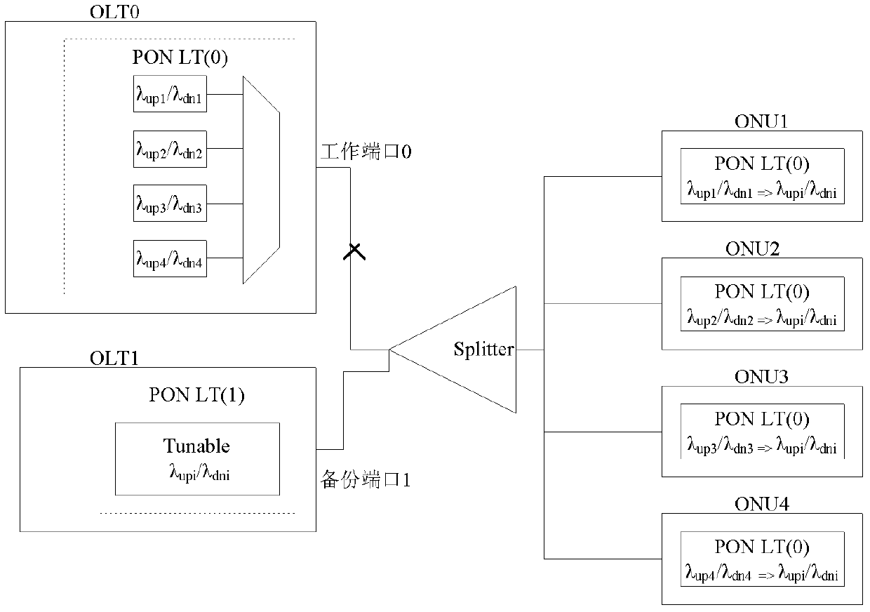
[0137] like image 3 as shown, image 3 It is a structure diagram of active / standby switchover. image 3 OLT 0 is the master OLT, and OLT 1 is the backup OLT. The working port 0 of the master OLT is connected to the optical splitter through the trunk fiber, the backup port 1 of the backup OLT is connected to the splitter through the backup fiber, and the other end of the splitter is connected to each ONU connection, wherein, the active OLT and the standby OLT transmit data with each ONU in real time through an optical splitter.
[0138] The main OLT, that is, OLT 0, includes at least 4 transceivers: transceiver 1, transceiver 2, transceiver 3, and transceiver 4. Each transceiver works on a working wavelength channel, and each wavelength channel uses a pair of upper and lower Uplink working wavelength, for example: Transceiver 1 works on working wavelength channel 1, and working wavelength channel 1 includes uplink working wavelength channel and downlink working wavelength ...
Embodiment 2
[0183] like Figure 5 as shown, Figure 5 It is another structure diagram of active / standby switchover. Figure 5 The structure of OLT 0 in image 3 The structure of the main OLT, ie OLT0, is the same. For the specific structure of OLT 0, please refer to image 3 description, which will not be repeated here.
[0184] exist Figure 5 In the architecture diagram of active-standby switchover, OLT0 predetermines the protection relationship between the working wavelength channels of OLT0. For example, the working wavelength channel 2 of the OLT is used as the backup wavelength channel of the working wavelength channel 3, that is, the working wavelength channel 2 and the working wavelength channel 3. A protection relationship is established between them, and the protection relationship is expressed in the PLOAM message as the identification information of the working wavelength channel and the identification information of the backup wavelength channel, and the message is sent ...
Embodiment 3
[0206] like Figure 7 as shown, Figure 7 It is another structure diagram of active / standby switchover. Figure 7 The structure of OLT 0 can be found in image 3 In the main use OLT, that is, the structure of OLT0.
[0207] Figure 7 The structure of the ONU in the image 3 The structure of the ONU in the middle is different. Each ONU supports two transceivers. If the two transceivers use different transceiver wavelengths, each ONU can work on two different wavelength channels at the same time. In this way, the OLT0 can flexibly adjust the service traffic on two different wavelength channels of the ONU according to the load conditions of each wavelength channel, so as to achieve the purpose of load balancing.
[0208] Any ONU includes at least 2 transceivers, and the transceivers work on two different working wavelength channels. For example, ONU1 includes transceiver 1 and transceiver 2. Transceiver 1 works on working wavelength channel 1, and working wavelength channel ...
PUM
 Abstract
Description
Claims
Application Information
 - R&D
- Intellectual Property
- Life Sciences
- Materials
- Tech Scout
- Unparalleled Data Quality
- Higher Quality Content
- 60% Fewer Hallucinations
Browse by: Latest US Patents, China's latest patents, Technical Efficacy Thesaurus, Application Domain, Technology Topic, Popular Technical Reports.
© 2025 PatSnap. All rights reserved.Legal|Privacy policy|Modern Slavery Act Transparency Statement|Sitemap|About US| Contact US: help@patsnap.com


