Notification method and equipment of positioning capability of evolution type base station

An evolved base station and positioning capability technology, applied in wireless communication, electrical components, etc.

Active Publication Date: 2011-03-30
DATANG MOBILE COMM EQUIP CO LTD
View PDF3 Cites 13 Cited by
  • Summary
  • Abstract
  • Description
  • Claims
  • Application Information

AI Technical Summary

Problems solved by technology

However, the disadvantage of the existing technology is that in the current LTE system, ther

Method used


Image

  • Notification method and equipment of positioning capability of evolution type base station
  • Notification method and equipment of positioning capability of evolution type base station
  • Notification method and equipment of positioning capability of evolution type base station

Examples


Embodiment 1

[0077] Figure 5 It is a schematic diagram of MME obtaining eNB positioning capability when S1 is established, Image 6 It is a schematic diagram of MME obtaining eNB positioning capability when S1 is updated. As shown in the figure, in the process of obtaining eNB positioning capability, MME can add The eNB positioning capability is an optional information element to carry the positioning capability of the eNB, so that the eNB can notify the MME of its positioning capability when S1 is established or when S1 is updated. The MME stores it after receiving it, and can determine the positioning capability of the eNB directly from the positioning capabilities of the subordinate eNBs stored by the MME when executing step 402 later.

Embodiment 2

[0079] Figure 7 It is a schematic diagram of obtaining the eNB positioning capability through OAM. As shown in the figure, in the process of obtaining the eNB positioning capability, the MME can maintain the positioning capability information of each eNB when the eNB is started, restarted, or the eNB positioning capability changes. The positioning capability of the eNB notifies the MME. The MME stores it after receiving it, and can determine the positioning capability of the eNB directly from the positioning capabilities of the subordinate eNBs stored by the MME when executing step 402 later.

[0080] 2. The implementation of the positioning capability of the interactive eNB between the MME and the E-SMLC in various positioning procedures, and the implementation of the positioning capability of the interactive eNB between the SLP and the E-SMLC.

[0081] In the process of exchanging eNB positioning capability information between MME and E-SMLC, the following scenarios will b...

Embodiment 3

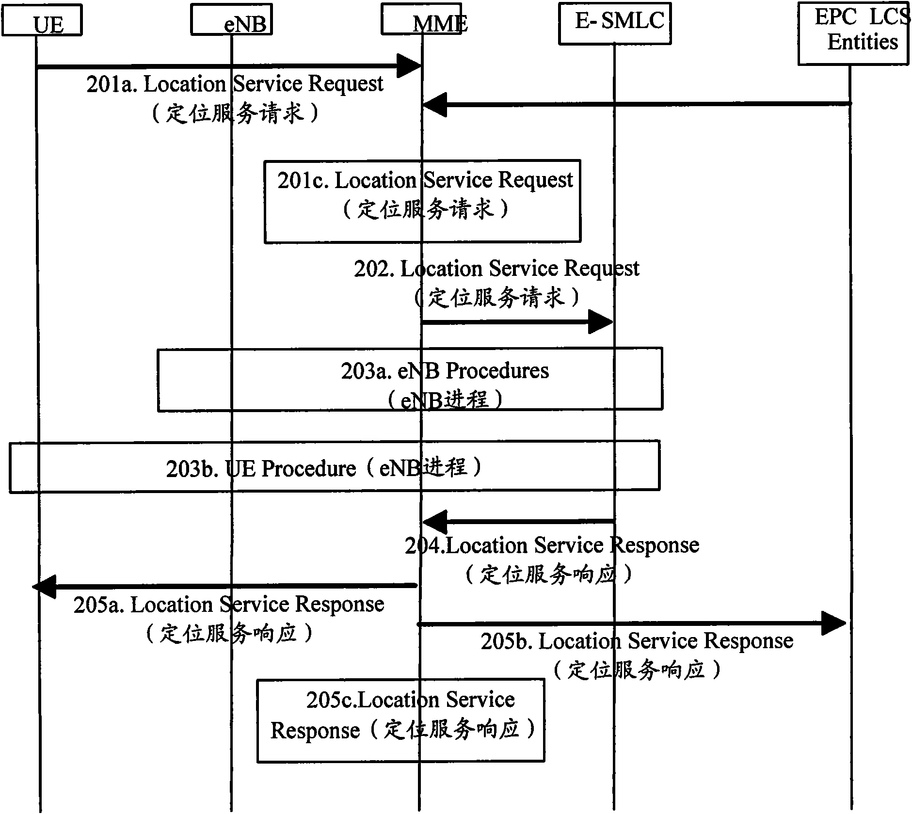
[0091] Figure 8 It is a schematic diagram of the eNB positioning capability notification during the control plane positioning initiation process. As shown in the figure, when the eNB positioning capability is notified during the control plane positioning initiation process, the following steps may be included:

[0092] Step 801, sending a positioning service request to the MME;

[0093] In this step, regardless of whether it is MO-LR, MT-LR or NI-LR, the final client will send a positioning service request to the MME;

[0094] Step 802, trigger a Service Request (service request); in the case of MO-LR and M-LR, when sending a positioning service request to the MME, the UE is already connected to the MME, so this step does not need to be performed; in the case of MT-LR , when sending a positioning service request to the MME, the UE may be in the ECM-IDLE state. At this time, the network side needs to trigger a ServiceRequest, establish a connection with the UE, and determine th...


PUM


Abstract

The invention discloses a notification method and equipment of the positioning capability of an evolution type base station. The method comprises the following steps of: determining the current service evolution type base station of user equipment by an mobility management entity; determining the positioning capability of the current service evolution type base station of the user equipment in the positioning capability of the subordinate evolution type base station of the mobility management entity; and notifying the positioning capability of the current service evolution type base station of the user equipment to the evolution type service moving position center by the mobility management entity. The invention ensures that the evolution type service moving position center can fully obtain the positioning capability of each node participating in the positioning for further selecting the proper positioning methods. Meanwhile, the mobility management entity notifies the positioning capability of the current service evolution type base station to the evolution service moving position center, and the signaling interaction between the evolution type base station and the evolution type service moving position center can be reduced.

Description

technical field [0001] The present invention relates to mobile communication technology, in particular to a method and equipment for notifying positioning capability of an evolved base station. Background technique [0002] figure 1 It is a schematic diagram of the positioning architecture of E-UTRAN (Evolution-Universal Terrestrial Radio Access Network, evolved global terrestrial radio access network), and the positioning architecture related to E-UTRAN is shown in the figure. The architecture supports both control plane positioning and user plane positioning. During the positioning process of the control plane, the target device is UE (User Equipment, user equipment), and the server on the network side is E-SMLC (Evolved Serving Mobile Location Centre, evolved service mobile location center). Through related control plane signaling, UE, eNB (evolved base station), MME (Mobility Management Entity, mobility management entity) and E-SMLC exchange information to complete the...

Claims


Application Information

Patent Timeline
IPC IPC(8): H04W64/00H04W68/00H04W88/08
Inventor 傅婧房家奕全海洋张大钧
Owner DATANG MOBILE COMM EQUIP CO LTD
Why Eureka
Try Eureka