
Cap unscrewing device

A technology of parts and studs, which is applied in the field of cap screwing device, can solve the problems of labor-saving, fixed size of capping device, and inability to adapt to the opening requirements of bottle caps of different sizes, etc., and achieve the effect of easy unscrewing

Inactive Publication Date: 2011-04-06
ELECTRIC POWER OF HENAN LUOYANG POWER SUPPLY
View PDF1 Cites 2 Cited by
  • Summary
  • Abstract
  • Description
  • Claims
  • Application Information

AI Technical Summary

Problems solved by technology

For young people, it doesn’t take too much effort to open the bottle cap, but it is very difficult for the elderly and women with relatively little strength to open the bottle cap, which brings some inconvenience to life
[0003] In order to solve this problem, various types of cap openers have emerged as the times require; however, there are cap openers that are fixed in size and cannot meet the opening requirements of bottle caps of different sizes; there are also cap openers that can be adjusted accordingly according to the size of the bottle cap. But the use effect is unsatisfactory: as disclosed in the Chinese patent ZL03223944.0 authorized on March 10, 2004, there are two front and rear clamping handles hinged by the clamping handle shaft, and the inner side of the clamping handle is provided with a cap screwer with sawtooth bars ; Although it can adapt to bottle caps of different sizes by adjusting the hinge angles of the front and rear handles during use, the front and rear handles generally form an ellipse, and any focal point of the ellipse does not coincide with the center of the bottle cap. The front and rear clamp handles are only in line contact with the bottle cap, and the contact area is limited, so it is not labor-saving to use, and if the position of the hand and the cap screwer changes during the capping process, the hand may be pinched.

Method used


Image

  • Cap unscrewing device
  • Cap unscrewing device

Examples


Embodiment Construction

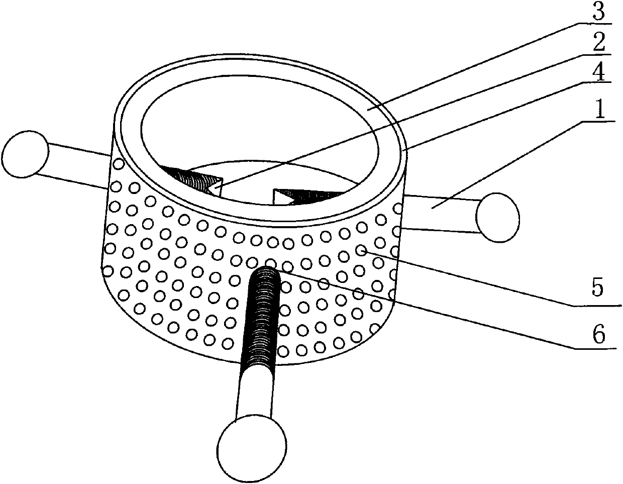
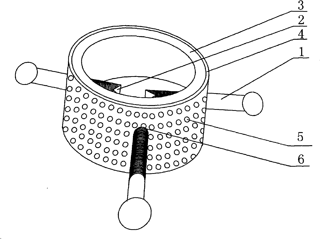
[0014] combine figure 1 , the hollow cylinder 3 is used as a rotating guide part, and three threaded holes 6 are evenly distributed along the circumference of the hollow cylinder 3, and the threaded holes 6 are respectively screwed with studs 1 to form adjustment parts; the three studs 1 are located inside the hollow cylinder 3 The top end constitutes the clamping part. Wherein, the length of one stud is longer than the other two studs, and the rotation of this stud facilitates the use of the relationship principle between force and torque to increase the torque when people unscrew the bottle cap. In order to better implement the present invention, the top end of the stud 1 positioned at the inner side of the hollow cylinder 3 is set as a V-shaped groove 2 parallel to the axis of the hollow cylinder, so that the contact points between the stud and the bottle cap as a clamping part increase , so as to increase the torque when people unscrew the bottle cap; similarly, a rubber ...


PUM


Abstract

The invention discloses a cap unscrewing device which comprises a clamp component, a regulation component and a rotating guide component and is characterized in that the rotating guide component is made into a hollow cylinder (3), three threaded holes (6) are uniformly distributed along the circumference direction of the hollow cylinder (3), screw bolts (1) are respectively screwed in the threaded holes (6) to form the regulation component, and the three screw bolts are positioned on the top end of the inner side of the hollow cylinder to form the clamp component. When a bottle cap needs to be unscrewed, the screwing distance between the three screw bolts and the threaded holes is correspondingly regulated according to the size of the outer diameter of the bottle cap so that a V-shaped notch arranged at one end of the three screw bolts is clamped on the outer ring of the bottle cap, and then, people rotate the hollow cylinder or push the long screw rod by hand to open the bottle cap. Through the implementation of the cap unscrewing device, the torque of people hand, which is exerted on the bottle cap, is increased, thus the bottle cap can be easily unscrewed. In addition, the goal of multifunction of one object is achieved through correspondingly regulating the opening degree of the clamp component via the regulation component according to different dimensions of the bottle caps.

Description

technical field [0001] The invention relates to an auxiliary tool for daily life, in particular to a cap twister for people to easily open bottle caps. Background technique [0002] In daily life, various bottles for containing food or beverages are common containers, and the bottle mouth and bottle cap are generally connected in a way similar to screws and nuts. For young people, the bottle cap can be opened without too much effort, but for the elderly and women with relatively little strength, it is a very difficult thing to open the bottle cap, which brings certain inconvenience to life. [0003] In order to solve this problem, various types of cap openers have emerged as the times require; however, there are cap openers that are fixed in size and cannot meet the opening requirements of bottle caps of different sizes; there are also cap openers that can be adjusted accordingly according to the size of the bottle cap. But the use effect is unsatisfactory: as disclosed in ...

Claims


Application Information

Patent Timeline
IPC IPC(8): B67B7/15
Inventor 丁亚伟李宏涛禹冰
Owner ELECTRIC POWER OF HENAN LUOYANG POWER SUPPLY
Learn More