
X-ray radiograph apparatus

An imaging device and X-ray technology, which is applied in the fields of radiological diagnosis instruments, medical science, diagnosis, etc., can solve the problems such as the inability to extend the insertion of the pallet and the inability to install the extension pallet.

Inactive Publication Date: 2012-11-21
SHIMADZU SEISAKUSHO CO LTD
View PDF1 Cites 0 Cited by
  • Summary
  • Abstract
  • Description
  • Claims
  • Application Information

AI Technical Summary

Problems solved by technology

However, as mentioned above, when stoppers are provided at the ends of the respective guide grooves, the protrusions of the extension pallets cannot be inserted from the ends of the respective guide grooves, and the extension pallets cannot be installed using the respective guide grooves.

Method used


Image

  • X-ray radiograph apparatus
  • X-ray radiograph apparatus
  • X-ray radiograph apparatus

Examples


Embodiment Construction

[0028] Hereinafter, examples of the present invention will be described.

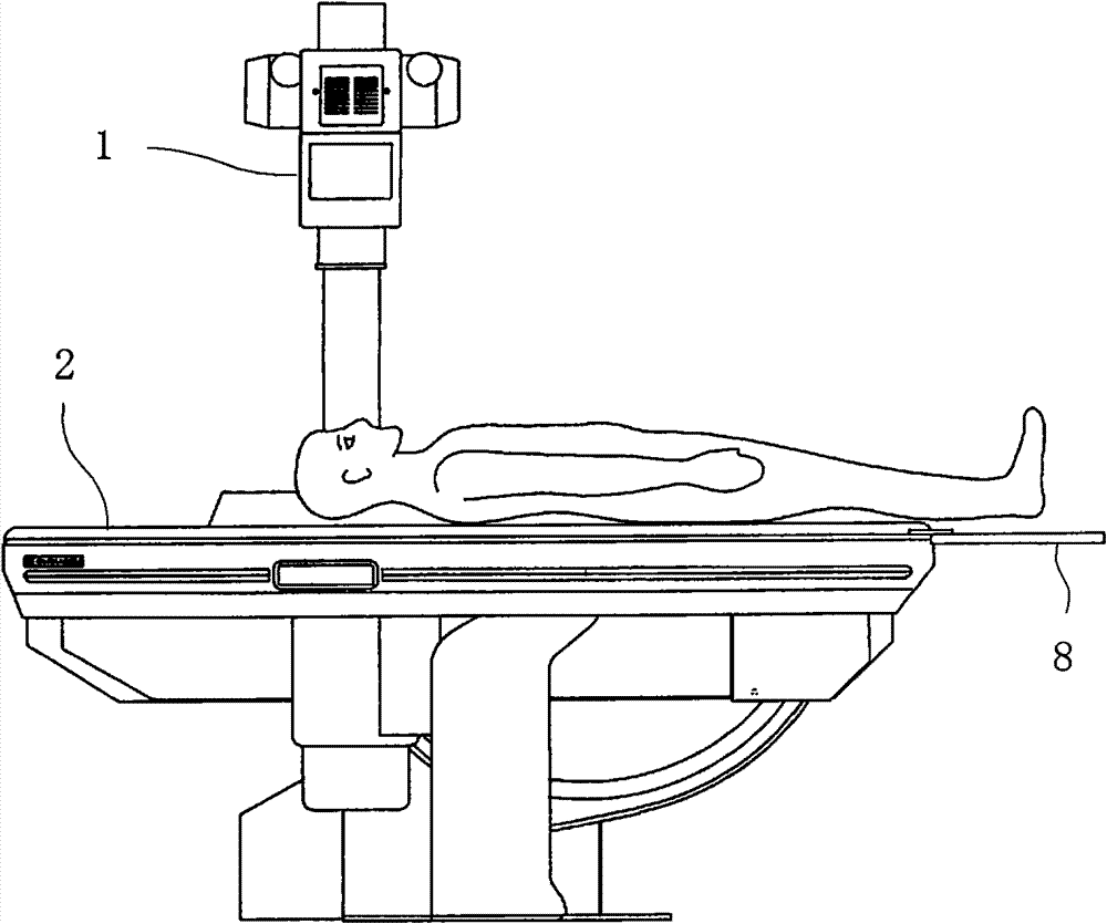
[0029] figure 1 The X-ray fluoroscopic imaging device of the present invention is shown. The device has an X-ray tube 1 for fluoroscopy imaging of a subject.

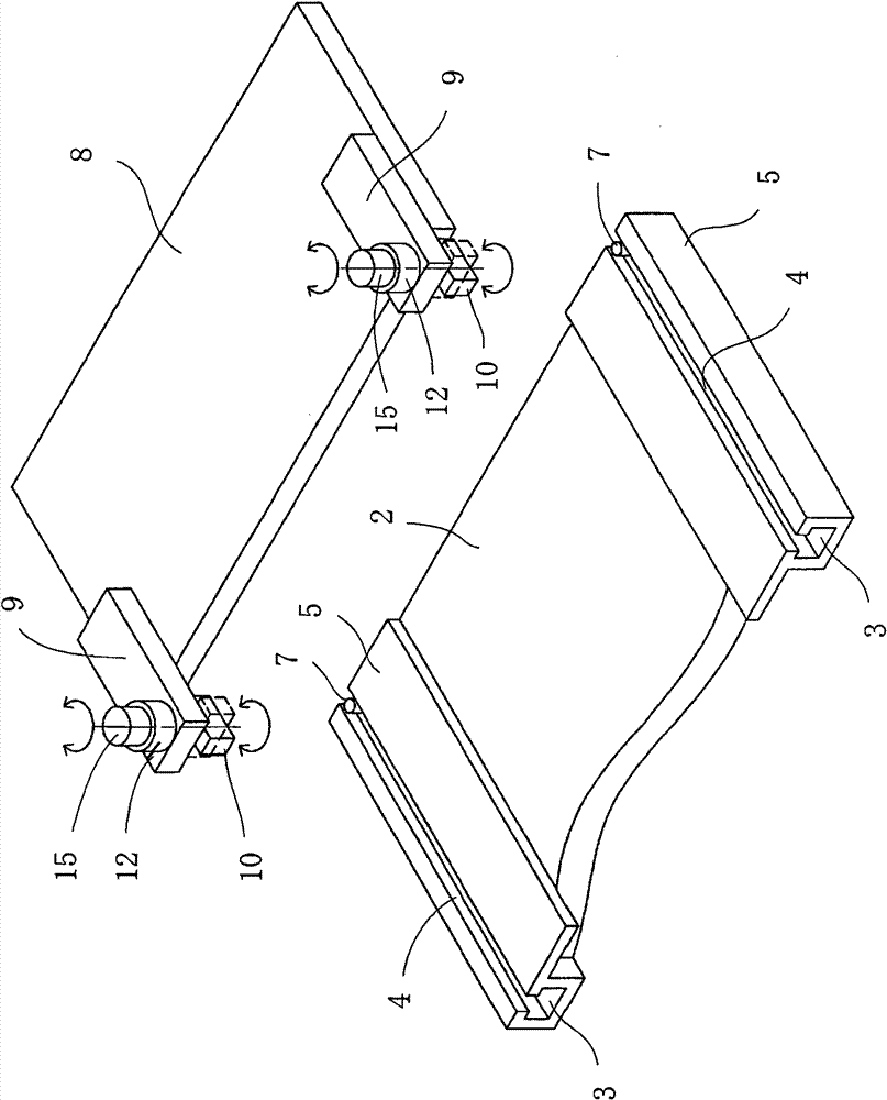
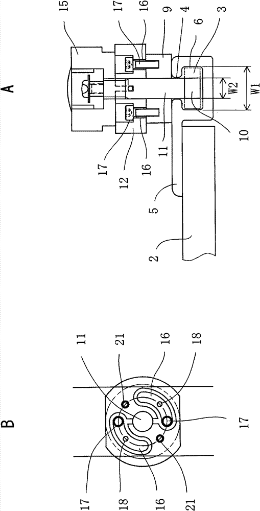
[0030] And, if figure 2 As shown, in this device, a pair of guide grooves 3 are provided on the pallet 2 for placing the body of the person under inspection. The guide grooves 3 have an opening 4 that opens upward. It extends in the length direction and is formed along the two side edges of the pallet 2 . In this embodiment, a pair of auxiliary parts 5 are arranged along the two side edges of the supporting board 2 , and the auxiliary parts 5 are fixed on the surface and sides of the supporting board 2 , and each guiding groove 3 is provided on each auxiliary part 5 . Such as image 3 As shown in A, the guide groove 3 has a rectangular cross-sectional shape, the inside of the guide groove 3 is formed by horizontal and vertical inner wall su...


PUM


Abstract

An X-ray radiograph apparatus with a top board (2) furnished with a pair of guide grooves (3) designed to allow fitting of a footstool by the guide grooves (3) and also allow fitting of an extension top board (8) by the guide grooves (3). In the apparatus, a pair of heads (10) are combined with a pair of rotary shafts. Each of the heads (10) is fitted to an inferior end of the respective rotary shaft. Upon abuttal of an extension top board (8) on the terminal edge of a top board (2), the heads (10) are inserted in the guide grooves (3) from openings (4) thereof and securely fitted in the interiors of the guide grooves (3). Thereafter, the rotary shafts and heads (10) are rotated by rotational operating means (12). The rotary shafts and heads (10) are rotated to an extent of 90 DEG.

Description

technical field [0001] The invention relates to an X-ray perspective imaging device. Background technique [0002] In an X-ray fluoroscopic imaging device having a pallet on which a person's body is placed, a pair of guide grooves are often provided on the pallet. The guide groove has an opening that opens upward, and the guide groove extends in the longitudinal direction of the pallet and is formed along both side edges of the pallet. The width of the opening is smaller than the width of the inside of the guide groove, and the opening is formed in the center of the guide groove in the width direction (see Patent Document 1). [0003] Therefore, for example, legs are provided on the shoulder pads used by the examinee, and the legs have a cross-sectional shape corresponding to the guide grooves. When the legs are inserted into the inside of each guide groove, the legs of the shoulder pad can Each guide groove moves so that its position can be adjusted arbitrarily. Furtherm...

Claims


Application Information

Patent Timeline
Patent Type & Authority Patents(China)
IPC IPC(8): A61B6/04
CPCA61B6/4411A61B6/04
Inventor 冈村贵由
Owner SHIMADZU SEISAKUSHO CO LTD
Learn More