Valve for a microfluidic system

A technology of microfluidic system and volume change, applied in the field of microfluidic system

Inactive Publication Date: 2011-04-06
KONINK PHILIPS ELECTRONICS NV
View PDF5 Cites 22 Cited by
  • Summary
  • Abstract
  • Description
  • Claims
  • Application Information

AI Technical Summary

Problems solved by technology

However, the valve will only work for a single event, since the paraffin will not return to the chamber

Method used


Image

  • Valve for a microfluidic system
  • Valve for a microfluidic system
  • Valve for a microfluidic system

Examples


Embodiment Construction

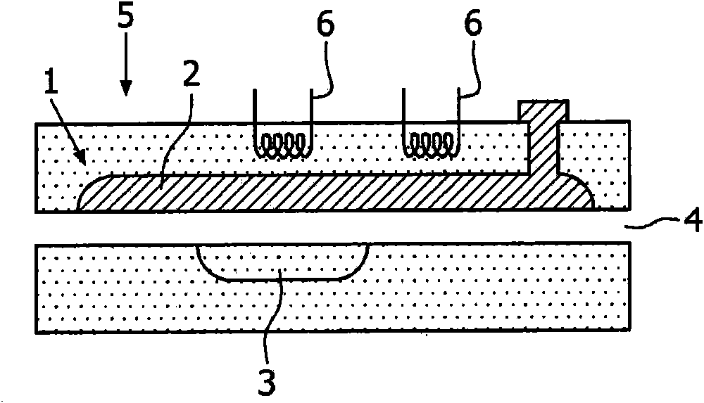
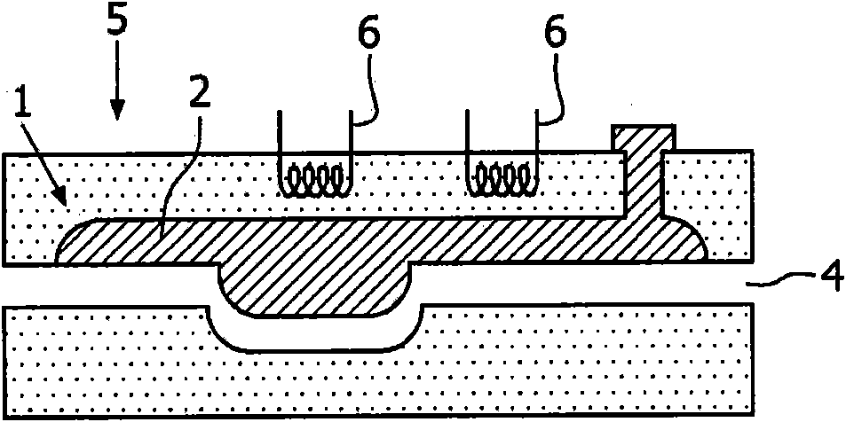
[0045] From Figures 1a and 1b, a valve according to a first preferred embodiment of the invention can be seen in a schematic side view. The valve comprises a medium container 1 containing an actuating medium 2 such as polyethylene glycol. With the help of an elastic membrane 4 made of PDMS and having a thickness between 100 μm and 300 μm, the actuating medium 2 in the medium container 1 is sealed against the chamber 3 to be closed and opened respectively by a valve.

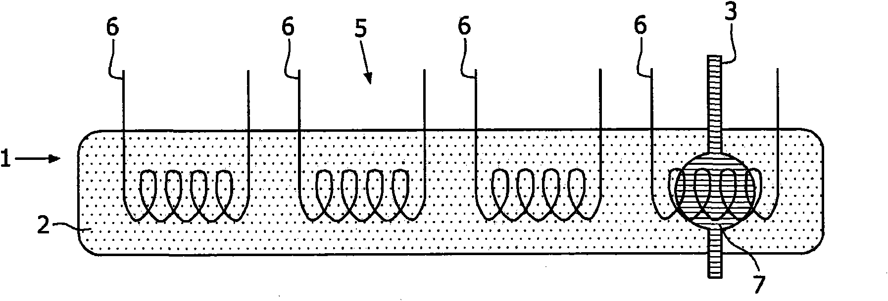
[0046] From FIGS. 1 a and 1 b it can further be seen that a heater arrangement 5 comprising two heaters 6 is provided. The heater 6 in the heater arrangement 5 of the preferred embodiment shown here is designed as a thin-film heater element so that the valve can be controlled electronically. By activating these heaters 6, a phase transition from solid / crystalline to liquid / amorphous and thus a volume expansion can be achieved, resulting in closing of the channel 3 by heating the heaters 6 of the heater arrangeme...


PUM


Abstract

The invention relates to a valve for opening and closing a channel (3) of a microfluidic system, respectively. According to the invention, the valve comprises an actuation medium (2) that undergoes a volume change with changing temperature; and a heater arrangement (5) for generating a temperature gradient in the actuation medium (2) with respect to the actuation medium's (2) distance relative to the channel (3); wherein due to an expansion or a contraction of the actuation medium (2) the channel (3) is closed or opened, respectively. When the heater arrangement (5) is activated in such a way that a higher temperature is generated in the actuation medium (2) which is nearer to the channel (3) and a lower temperature is generated in the actuation medium (2) which is further away from the channel (3) the valve can be closed and vice versa. Accordingly, such a valve for a microfluidic system is provided which can be reliably actuated during a long time of use.

Description

technical field [0001] The present invention relates to the field of microfluidic systems, in particular to valves for opening and closing channels of microfluidic systems, respectively. Background technique [0002] Especially integrated portable microbiological systems for rapid digital diagnostic tests (RDTs) require independently operated microvalves to control the transfer of liquid samples for complex and parallel functions. However, conventional microvalves are cumbersome to fabricate due to the fabrication steps of the layers or the need for an external pressure source to operate them. [0003] A key element in such a system is an integrated active valve, which preferably can be actuated without an external pump, enabling a portable biochemical system for point-of-care / as-need testing. Such systems are generally based on thermal expansion / contraction of polyethylene glycol (PEG) or melting / crystallization of paraffin. However, the performance of microvalves based o...

Claims


Application Information

Patent Timeline
Patent Type & Authority Applications(China)
IPC IPC(8): B01L3/00F16K99/00
CPCF16K99/0061B01L2300/0627B01L2400/0677B01L2200/147F16K99/0001F16K2099/0084B01L2200/146F16K99/0044G01N2035/00247B01L3/502738B01L2300/1838F16K99/0026B01L2400/0638Y10T137/6606
Inventor R·库尔特E·皮特斯R·彭特曼D·J·布罗尔C·J·巴克豪斯
Owner KONINK PHILIPS ELECTRONICS NV
Why Eureka
Try Eureka