Mobile terminal having photographing control function and photographing control system

A technology for mobile terminals and control pairs, which is applied to equipment with functional cameras, transmission systems, components of TV systems, etc., and can solve problems such as out-of-focus, mobile terminal movement, and image blur

A technology for mobile terminals and control pairs, which is applied to equipment with functional cameras, transmission systems, components of TV systems, etc., and can solve problems such as out-of-focus, mobile terminal movement, and image blur

CN102014198AInactive Publication Date: 2011-04-13PANTECH CO LTD

Image

  • Mobile terminal having photographing control function and photographing control system
  • Mobile terminal having photographing control function and photographing control system
  • Mobile terminal having photographing control function and photographing control system

Examples


Embodiment Construction

[0026] The present invention will be described more fully hereinafter with reference to the accompanying drawings, in which exemplary embodiments of the invention are shown. However, the invention may be embodied in different forms and therefore the invention should not be construed as limited to the embodiments set forth herein. Rather, these exemplary embodiments are provided so that this disclosure will be thorough, and will fully convey the scope of the invention to those skilled in the art. Like numbers denote like elements in the figures.

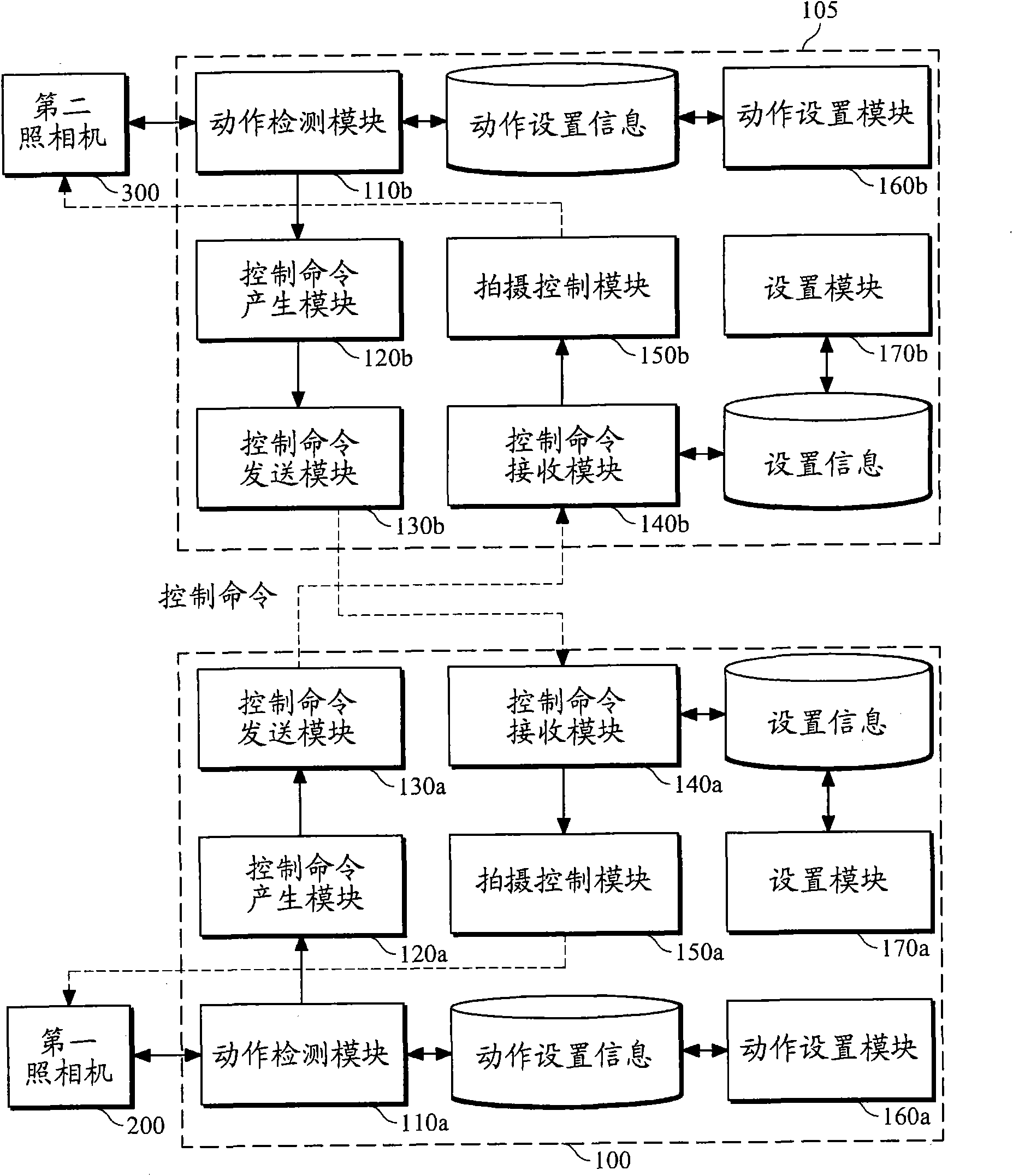
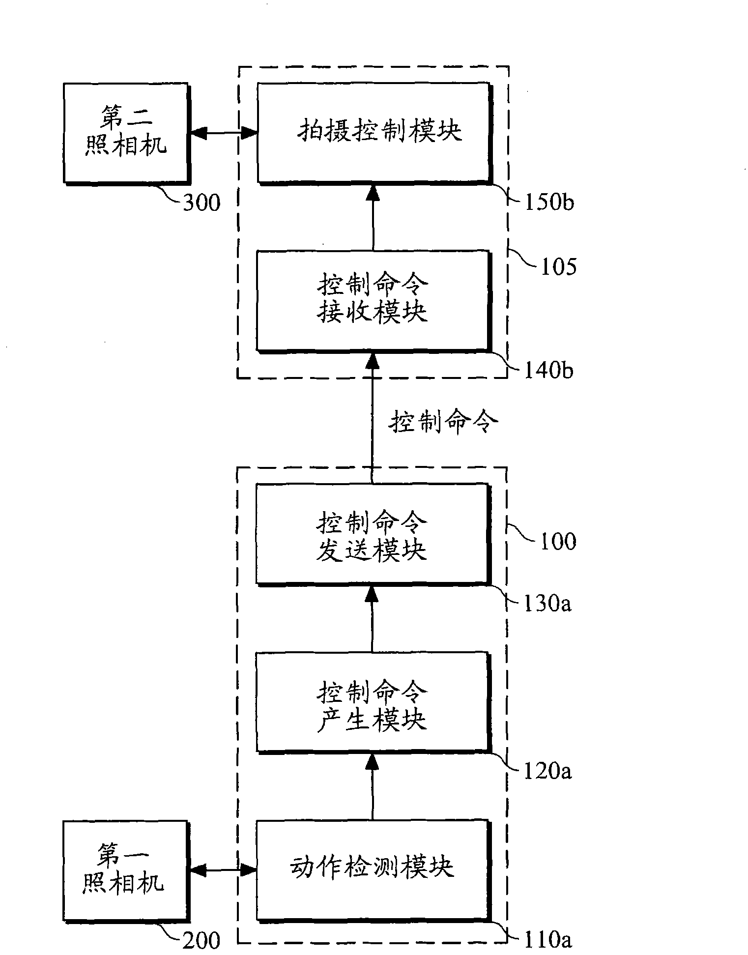
[0027] figure 1 is a user's mobile terminal 100 having a shooting control function based on an image recognition technology and its counterpart mobile terminal 105 according to the first exemplary embodiment of the present invention. The user's mobile terminal 100 with a shooting control function includes a motion detection module 110a, a control command generation module 120a, a control command sending module 130a, a control comman...


PUM


Abstract

The invention discloses a mobile terminal having a photographing control function and a photographing control system. In a mobile terminal having a photographing control function based on an image recognition technique and a photographing control system employing an image recognition technique, a specific action is detected from a user image taken by one camera, and the operation of another camera or the processing of an image taken by the camera is controlled when the specific action has been detected, thereby controlling photographing without direct physical manipulation of a user.

Description

technical field [0001] The present application relates to shooting control technology in a mobile terminal. Background technique [0002] Conventionally, in a mobile terminal having both a front camera and a rear camera, a user issues shooting control commands such as zooming in and zooming out by manipulating buttons or a touch screen. Meanwhile, in the case of a conventional mobile terminal having a video communication function, a user issues a shooting control command by manipulating a button or a touch screen, but cannot control a counterpart's camera. [0003] It is very inconvenient for a user to input shooting control commands such as zoom in and zoom out by physically manipulating buttons and a touch screen in a camera-equipped mobile terminal during shooting. In addition, when a user manipulates a button or a touch screen, the mobile terminal may be slightly moved, so that an image may be blurred or out of focus. Contents of the invention [0004] Exemplary embo...

Claims


Application Information

Patent Timeline
13 Apr 2011
Publication
CN102014198A
IPC
H04M1/725; H04M1/02; H04N5/232; G03B15/00; G03B17/00; H04M1/72439; H04M1/72454; H04N23/90
CPC
H04N5/247; H04M1/72569; H04N2007/145; H04M2250/52; H04N21/41407; G06F3/017; G06F3/012; H04N5/23206
Inventors
金炯伯; 李圣范