Connector assembly

A technology of connectors and assemblies, applied in packaging, connecting tubes, medical containers, etc., which can solve the problems of medical workers who are accidentally punctured by needle points and transfer liquids

Inactive Publication Date: 2011-04-13
TERUMO KK
View PDF7 Cites 14 Cited by
  • Summary
  • Abstract
  • Description
  • Claims
  • Application Information

AI Technical Summary

Problems solved by technology

In this case, the liquid agent may scatter from the exposed needle point and adhere to the medical worker, etc., or the medical worker may be accidentally punctured by the needle point, and there is a problem that the liquid agent cannot be safely and reliably transferred through the connector.

Method used


Image

  • Connector assembly
  • Connector assembly
  • Connector assembly

Examples


no. 1 approach

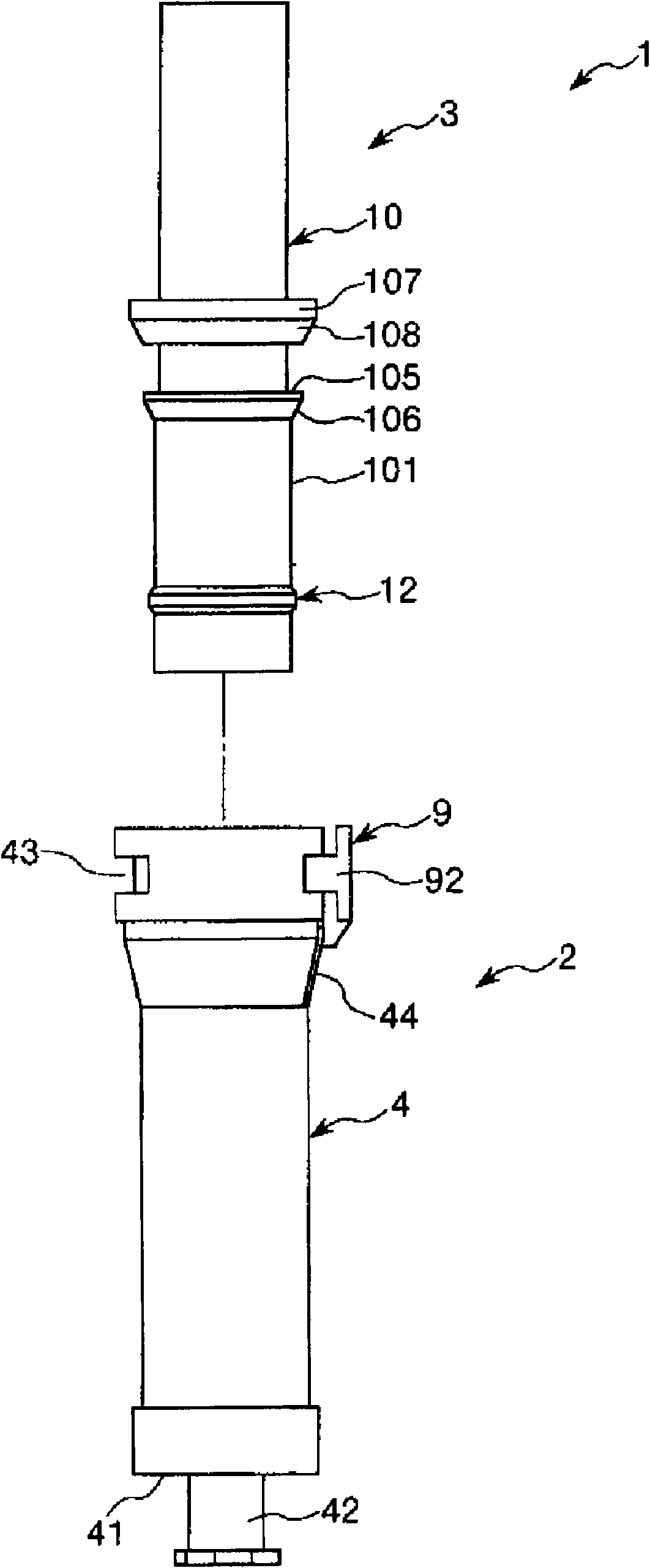
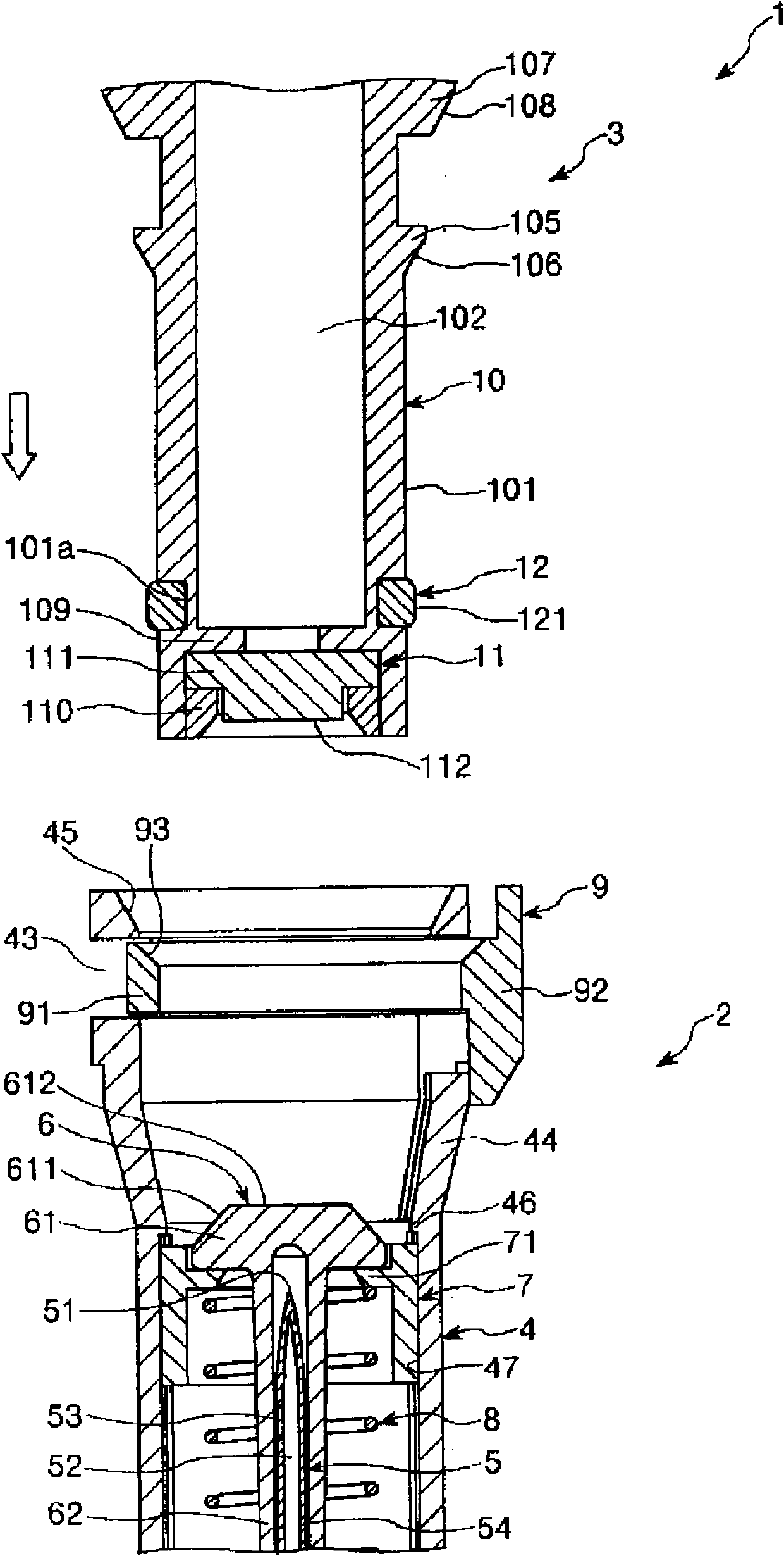
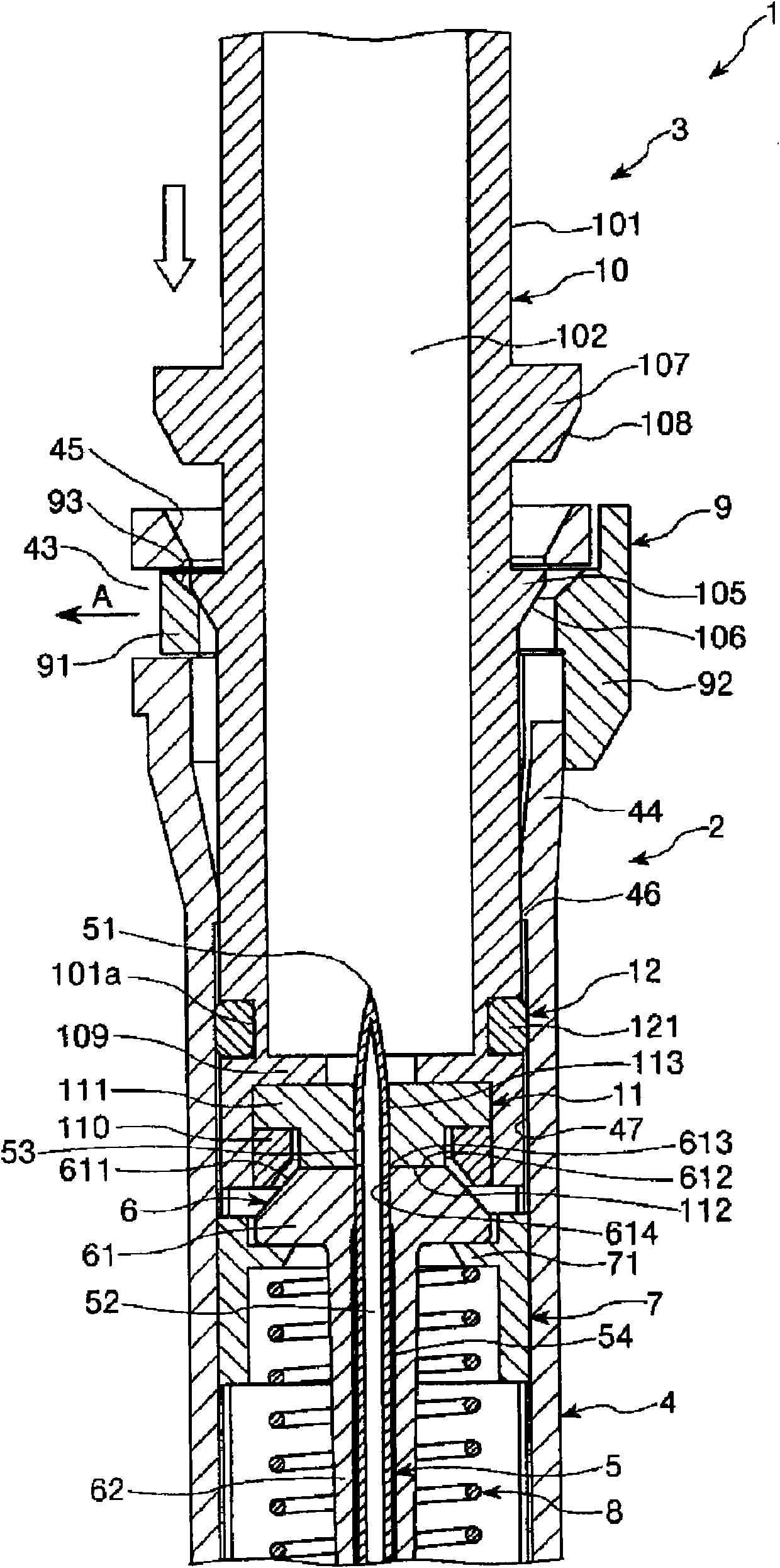
[0078] figure 1 It is an exploded side view of the connector assembly (first embodiment) of the present invention; Figure 2 ~ Figure 4 They are respectively longitudinal sectional views showing the process until the first connector and the second connector in the connector assembly of the present invention are brought into an assembled state (mounted state); Figure 5 ~ Figure 7 means until the Figure 4 A longitudinal sectional view of the process until the shown (assembled state) connector assembly becomes a disassembled state; Figure 8 It is a longitudinal sectional view showing the first connector in the connector assembly (first embodiment) of the present invention; Figure 9 It is a longitudinal sectional view showing the second connector in the connector assembly (first embodiment) of the present invention; Figure 18 is installed in the Figure 8 Partial longitudinal section of the syringe on the first connector shown. In addition, for the convenience of explana...

no. 2 approach

[0163] Figure 10 It is a side view showing the second connector in the connector assembly (second embodiment) of the present invention; Figure 11 It is a cross-sectional view showing the first connector body and the second connector body in an assembled state in the connector assembly (second embodiment) of the present invention.

[0164] Hereinafter, a second embodiment of the connector assembly of the present invention will be described with reference to these drawings, but differences from the above-mentioned embodiment will be mainly described, and descriptions of the same matters will be omitted.

[0165] This embodiment is the same as the first embodiment except that the structure of the second connector body is different.

[0166] exist Figure 10 , Figure 11 In the shown second connector main body 10A, six ribs 13 formed along the longitudinal direction are integrally formed on the outer peripheral portion 101 . Such as Figure 11 As shown, the tops 131 of the ...

no. 3 approach

[0171] Figure 12 It is a partial longitudinal sectional view showing the first connector body and the second connector body in the connector assembly (third embodiment) of the present invention.

[0172] Hereinafter, a third embodiment of the connector assembly of the present invention will be described with reference to these drawings, but differences from the above-mentioned embodiment will be mainly described, and description of the same items will be omitted.

[0173] This embodiment is the same as the first embodiment except that the structures of the first connector body and the second connector body are different.

[0174] Such as Figure 12 As shown, four helical grooves 48 are formed in the inner peripheral portion 47 of the first connector body 4B. In addition, in the second connector main body 10B, four protrusions 14 are protrudingly formed at the front end portion of the outer peripheral portion 101 . In the assembled state, the first connector 2 and the secon...


PUM


Abstract

A connector assembly is provided with a first connector equipped with a first connector body, a hollow needle supported on the inner side of the first connector body and having a side hole (53), and a first sealing member having a head which can be pierced through by the hollow needle; a second connector equipped with a second connector body and also with a second sealing member which can, when in a mounted state, be pierced through by the hollow needle; and a close-contact maintaining means which can, when in the mounted state, maintain that the head and the second sealing member are in close contact with each other. When the second connector becomes pulled out of the first connector, the head and the second sealing member are held in close contact with each other by the close-contact maintaining means until the hollow needle is pulled out of the second sealing member.

Description

technical field [0001] The present invention relates to connector assemblies. Background technique [0002] Usually, anticancer agents, immunosuppressants, and other drugs that are dangerous if medical workers accidentally touch them are contained in a powder state in a vial container (medicine storage container) whose mouth is sealed with a rubber stopper. [0003] When taking out medicines from such vial containers, the following operations are performed. [0004] First, the mouth of the vial container and the mouth of the syringe from which the solution for dissolution was dispensed are connected via a connector (see Patent Document 1). Next, in this connected state, the solution for dissolving is injected into the vial container from the syringe. Then, the drug is uniformly dissolved in the dissolving liquid by performing a pumping operation, shaking the vial container, or the like. Next, the solution for dissolution in which the drug is dissolved (hereinafter referre...

Claims


Application Information

Patent Timeline
Patent Type & Authority Applications(China)
IPC IPC(8): A61M39/02A61M39/10A61M39/26A61J1/10
CPCA61J2001/201A61J1/2096A61M2039/1072A61M39/0606A61M2039/267A61M2039/1077A61M39/1011A61M39/04A61M5/162A61J2001/2051A61J1/201A61J1/2051
Inventor 平沼隆明竹本昌史冈部博光
Owner TERUMO KK
Why Eureka
Try Eureka