Glass plate conveyance pallet

A glass plate and glass cover technology, which is applied to conveyor objects, containers, trolleys, etc., can solve the problems of loose strapping, easy deflection of the central part, and deviation of the position of the glass plate.

Active Publication Date: 2010-04-14
AGC INC
View PDF5 Cites 0 Cited by
  • Summary
  • Abstract
  • Description
  • Claims
  • Application Information

AI Technical Summary

Problems solved by technology

However, when the glass plates are placed upright, the central part tends to bend due to the weight of the glass plates, and even if they are securely bound, the binding tape, etc. will become loose, and the glass plates will slide during transportation, causing misalignment. move, there is a risk of breakage

Method used


Image

  • Glass plate conveyance pallet
  • Glass plate conveyance pallet
  • Glass plate conveyance pallet

Examples


Embodiment 1

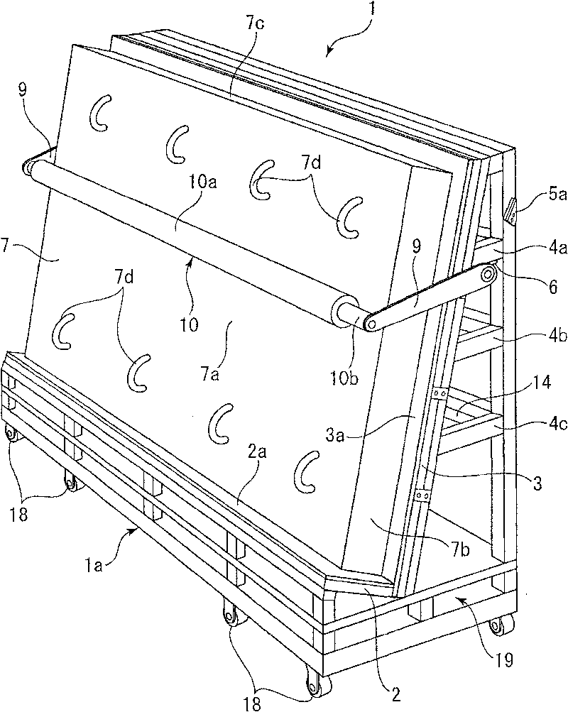
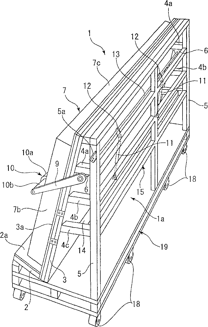
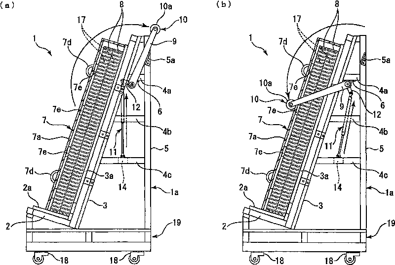
[0111] figure 1It is a perspective view showing the structure of the front side of the glass plate conveying tray in Example 1 of the present invention, figure 2 It is a perspective view showing the structure of the rear side of the glass plate conveyance bracket, image 3 It is a partially cutaway side view showing the side surface structure of the glass plate transport bracket, (a) is a side view showing the state where the packing box is released from the central rod, and the packing box accommodates a plurality of glass plates covered with a glass cover. The glass plate, (b) is a side view showing the state in which the center rod is moved downward and the sealing box is held by the center rod through the glass cover.

[0112] This glass plate conveyance pallet (hereinafter referred to as a conveyance pallet) can vertically stack and convey a plurality of glass plates, and is used as a trolley for conveying and moving glass plates. Therefore, when Embodiment 1 of the pr...

Embodiment 2

[0127] Figure 4 It is a perspective view showing the structure of the front side of the glass plate conveying tray in Example 2 of the present invention, Figure 5 It is a partially cutaway side view showing the side structure of the glass plate conveyance bracket, Figure 5 (a) is a side view showing a state in which a packaging box containing a plurality of glass plates covered by a glass cover provided with a reinforcing bar is released from the central rod, Figure 5 (b) is a side view which shows the state which moved the central rod downward and contacted the reinforcement rod, and held the packaging box by the central rod via the glass cover. In addition, in the following embodiment 2, the parts having the same configuration as those of the above-mentioned embodiment 1 are given the same symbols and their detailed descriptions are omitted.

[0128] The cover body 7 covering the packaging box 8 is formed of a hard plastic member, and is formed to be light and strong. ...

Embodiment 3

[0134] As the way of placing the glass plate 17 on the bracket main body 1a, it is not limited to Embodiments 1 and 2, according to Image 6 Example 3 will be described. In addition, in the following embodiment 3, the parts having the same configuration as those of the above-mentioned embodiment 1 are given the same symbols to omit their detailed description.

[0135] first, Image 6 (a) A side view showing a modified example of directly holding the glass plate 17 with the central rod 10, placing the bottom of each glass plate on the stage 2, and placing the rear surface 17c of the last glass plate on the rear support 3, so that multiple glass plates are laminated. Further, the central rod 10 directly contacts the vicinity of the central portion 17a of the frontmost glass plate 17' from above by swinging the support arm 9, and the laminated glass plate 17 is supported on the stage 2 side.

[0136] Furthermore, even when the laminated glass plates 17 are directly supported b...


PUM


Abstract

A glass plate conveyance pallet with good operability, where, even when glass plates are vertically layered on the conveyance pallet, no sag occurs about the center of the glass plates and sliding between the glass plates does not occur even in movement. Because a center bar (10) is made to be in contact with the vicinity of a central section (17a) of a cover body (7) covering glass plates (17) that are vertically layered, sag in the vicinity of the central section (17a) of the individual glass plates (17) that are layered and supported can be suppressed by the center bar (10). As a result, even during transfer of the conveyance pallet (1), movement of the layered and supported glass plates (17) is reliably prevented to prevent breakage of the glass plates (17). Further, the fixation and release of the layered and supported glass plates (17) by the center bar (10) can be made by swing motion of a support arm (9), so that operation is easy and, even if the number of layers of the glassplates (17) is increased or decreased, such a change can be easily coped with by changing the swing radius of the center bar (10).

Description

technical field [0001] The present invention relates to a glass plate conveyance bracket which transports a plurality of glass plates vertically stacked and supported on a bracket main body. Background technique [0002] Conventionally, there is known a transport bracket in which a plurality of metal plates are laid horizontally and stacked for transport. This type of transport bracket is provided with a plurality of pillars upright at both ends in the width direction of the bracket substrate. The restriction plate that fits in the slit that is provided with on the pillar is placed on the multiple metal plates stacked on the bracket main board, which can prevent the metal plate from sliding caused by the shaking of multiple metal plates (for example, refer to the patent Literature 1). [0003] Patent Document 1: Japanese Unexamined Patent Publication No. 9-30526 (refer to paragraphs 0010, 0011, and figure 2 , 4 ) [0004] However, with regard to Patent Document 1, it is ...

Claims


Application Information

Patent Timeline
Patent Type & Authority Patents(China)
IPC IPC(8): B65D85/48B65D19/38B65D19/44B65D85/00
CPCB62B2301/08B65G49/062B65D85/48B62B3/108B62B3/04B65D19/38B65D19/44B65D85/00
Inventor 平林孝夫布施裕児中元谦一
Owner AGC INC
Why Eureka
Try Eureka